Twin Scan 4 FAQ
What are the differences from Twin Scan 3 ABS to Twin Scan 4?
The main difference from Twin Scan 3 ABS to Twin Scan 4 is extended CANbus commands that allow many features that the dealer performs with the digital technician. The list includes the ability to program remote key fobs & disable the security system, change engine idle speed, test engine controls, calibrate the speedometer, activate BCM lights, and many more features. Please download the latest software from our website. All of the menus can viewed to see all of the new features.
Explain the procedure used to bleed ABS brake systems with the Twin Scan series?
Harley-Davidson® currently has three versions of ABS. The original ABS is used on 2008-2013 touring models. A second version, with independent front and rear hydraulic control units, was introduced on 2011 Softail® models. A third version was introduced on 2012 Dyna® models. A special command sequence is required to properly bleed the ABS when any brake service is performed. The new Twin Scan ABS series feature this capability. The Twin Scan II ABS can be used with the 2008-2013 touring models that have the J1850 data bus. The Twin Scan 3 ABS and the Twin Scan 4 can be used with 2011-2013 Softail® and 2012-2013 Dyna® models that have the CAN data bus. While the commands sent on the bus and timing differ with each ABS version, the bleeding procedure explained below is the same.

ABS – Normal Hydraulic Brake Operation
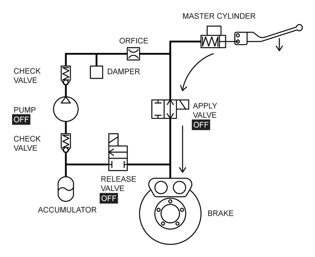
The figure above shows a hydraulic diagram for the ABS. Besides the conventional master cylinder and disk brake, the system has apply and release solenoid valves, pump, accumulator, check valves, surge damper, and a flow restriction orifice. The ABS ECM controls the apply and release solenoid valves and the pump motor. When the ABS is not active, all these devices are off. The release valve is normally closed (no flow) and the apply valve is normally open (flow). When the brake lever is pressed, fluid flows from the master cylinder through the apply valve to the disk brake as shown by the flow arrows. This mode of operation is the same as a conventional hydraulic brake system.
Operation of the ABS under wheel slippage conditions is very complex and beyond the scope of this Tech FAQ. Additional information can be found in the Bosch publication Driving-Safety Systems (2nd Edition) translation by Peter Girling.
An initial manual (conventional) brake bleeding precedes the ABS bleeding procedure. The actual ABS bleeding procedure consists of three steps shown in the figures below. After the third step, a final manual brake bleeding releases any air bubbles that were trapped within the ABS.
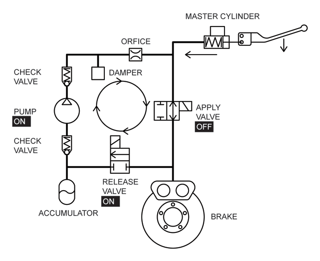
1. Release step. The release valve and pump are on. All valves now allow flow. Fluid is pumped in a loop around the system. The technician applies pressure to the brake lever and causes the master cylinder to empty through both valves into the accumulator. The brake lever collapses down.
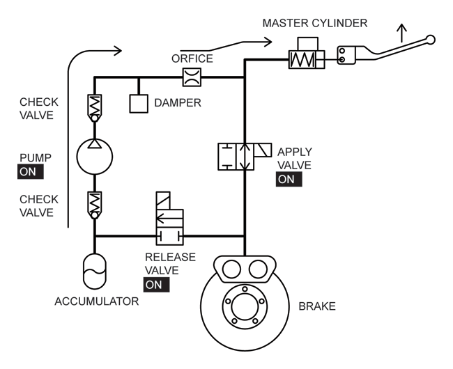
2. Return step. Both valves and the pump are on. Turning on the apply valve blocks flow. Fluid is pumped from the accumulator back into the master cylinder and the brake lever is pushed back up.
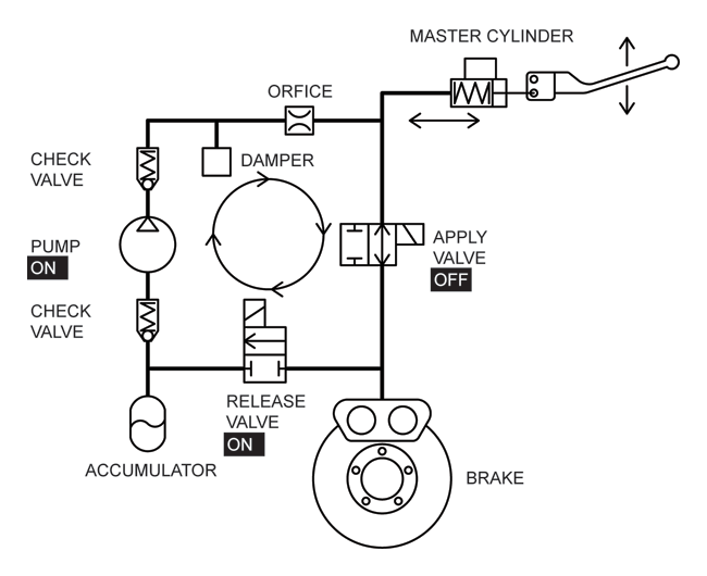
3. Pumping step. The release valve and pump are on. All valves now allow flow. Fluid is pumped in a loop around the system. The technician manually pumps the brake lever causing flow back and forth that helps any remaining air bubbles escape from the ABS.

ABS Bleeding – Release Step

ABS Bleeding – Return Step

ABS Bleeding – Pumping Step
How can I use Excel spreadsheets with the Screamin’ Eagle® Pro Super Tuner (SEST) and Dynojet® Power Commander®?
If you have Microsoft Office with Excel, you can directly copy and paste data from the Twin Scan 4 software to an Excel spreadsheet and then copy and paste from the Excel spreadsheet into the tuning program. We have prepared sample Excel spreadsheets that you can download and use for this purpose. Before you try using this approach, you need to make a realistic assessment of your skill level as far as using Excel. Please note that we cannot provide tech support for Excel related issues or help you with individual tuning files. However, we do appreciate comments, suggestions, and feedback.
The sample Excel spreadsheets are in a ZIP archive file that you can download by clicking on the link below.
Sample Excel Spreadsheets for use with Twin Scan 4
Screamin’ Eagle® Pro Super Tuner (SEST)
The current version SEST software supports copy and paste operations. Spreadsheets for use with the SEST have a filename starting in “TS4_ST.” There are two types of spreadsheets. The first type (with “AFR” in the filename) has corrections based on Twin Scan 4 AFR data. The second type (with “VE” in the filename) is based on Twin Scan 4 VE corrections. The last section of the filename identifies the table format (such as “13×19”) and corresponds to the table formats available in the Twin Scan 4 software. Use the following guidelines to choose between “AFR” or “VE” versions:
SEST Corrections Based on Twin Scan AFR Data
This approach is recommended for only for applications without original equipment oxygen sensors. In the Twin Scan 4 software, select AFR Data Display. The Twin Scan 4 table will show the actual AFR values logged by the system. Start the SEST program and open the Excel spreadsheet. The first sheet is Base VE values. Copy the working VE values from the SEST program to the Base VE sheet. The second sheet is TSCAN AFR Data. Copy the AFR Data from the Twin Scan 4 to the TSCAN AFR Data sheet. The third sheet is Target AFR. Edit the values in this sheet to your desired target AFR values. The last sheet is Corrected VE. These are the calculated VE values required to achieve the target AFR values. Copy the corrected VE values back into the SEST program. The cells in this last sheet have calculation formulas. Be careful not to type anything into these cells as this will corrupt the formulas.
SEST Corrections Based on Twin Scan VE Data
This approach is recommended for all applications with original equipment oxygen sensors. Remember that with these applications, you can only change idle and part throttle AFR values with the SEST. Otherwise, closed loop AFR control in the ECM will counteract any changes you make at idle and part throttle. Start by editing the AFR table in the SEST program, then reflash the ECM, and log data. You can also use this approach for any applications where you want to keep the existing AFR values in the SEST AFR table. In the Twin Scan 4 software, select both VE Percent Correction Display and Use AFR Command as Target. The Twin Scan 4 table will show the VE corrections required to achieve the AFR values commanded by the ECM. Start the SEST program and open the Excel spreadsheet. The first sheet is Base VE values. Copy the working VE values from the SEST program to the Base VE sheet. The second sheet is TSCAN VE Correction. Copy the VE correction data from the Twin Scan 4 to the TSCAN VE Correction sheet. The last sheet is Corrected VE. These are the calculated VE values required to achieve the target AFR values. Copy the corrected VE values back into the SEST program. The cells in this last sheet have calculation formulas. Be careful not to type anything into these cells as this will corrupt the formulas.
Dynojet® Power Commander® (PC)
The current version of the PC software supports copy and paste operations. Spreadsheets for use with the PC have a filename starting in “TS4_PC.” There are two types of spreadsheets. The first type (with “AFR” in the filename) has corrections based on Twin Scan 4 AFR data. The second type (with “VE” in the filename) is based on Twin Scan 4 VE corrections. The last section of the filename identifies the table format (such as “10×13”) and corresponds to the table formats available in the Twin Scan 4 software. Use the following guidelines to choose between “AFR” or “VE” versions:
PC Corrections Based on Twin Scan AFR Data
This approach is recommended for only for applications without original equipment oxygen sensors where you want to change AFR values. In the Twin Scan 4 software, select AFR Data Display. The Twin Scan 4 Table will show the actual AFR values logged by the system. Start the PC program and open the Excel spreadsheet. The first sheet is Base Fuel values. Copy the fuel table values from the PC to the Base Fuel sheet. The second sheet is TSCAN AFR Data. Copy the AFR Data from the Twin Scan 4 to the TSCAN AFR Data sheet. The third sheet is Target AFR. Edit the values in this sheet to your desired target AFR values. The last sheet is Corrected Fuel. These are the calculated fuel values required to achieve the target AFR values. Copy the corrected fuel values back into the PC. The cells in this last sheet have calculation formulas. Be careful not to type anything into these cells as this will corrupt the formulas.
PC Corrections Based on Twin Scan VE Data
This approach is recommended for all applications with original equipment oxygen sensors. Remember that with these applications, closed loop AFR control in the ECM will counteract any attempt to change AFR values at idle and part throttle. Use this approach to keep the existing AFR values commanded by the ECM, but make corrections for engine modifications. In the Twin Scan 4 software, select both VE Percent Correction Display and Use AFR Command as Target. The Twin Scan 4 table will show the VE (same as percent fuel) corrections required to achieve the AFR values commanded by the ECM. Start the PC program and open the Excel spreadsheet. The first sheet is Base Fuel values. Copy the fuel table values from the PC to the Base Fuel sheet. The second sheet is TSCAN VE Correction. Copy the VE correction data from the Twin Scan 4 to the TSCAN VE Correction sheet. The last sheet is Corrected Fuel. These are the calculated fuel values required to achieve the target AFR values. Copy the corrected fuel values back into the PC. The cells in this last sheet have calculation formulas. Be careful not to type anything into these cells as this will corrupt the formulas.
Some new 2014 SEST tables have rows in 125 RPM increments to 3000 RPM. How do I handle this?
Logging AFR data with rows in 125 RPM increments is difficult because available chassis dyno systems cannot hold RPM within the ±62.5 RPM range that would be required. An easy solution is to use a special spreadsheet that interpolates Twin Scan 4 AFR data between rows with 250 RPM increments. These spreadsheets are identified by “interpolated” in the filename. The interpolated data is highlighted in yellow. For example, the file “TS4_ST_VE_Calc_13x27_Interpolated.xls” allows tuning SEST “13 x 27” (TPS columns and RPM rows) tables using Twin Scan 4 VE correction data from a “13×19” table.
Your spreadsheet table rows and columns don’t precisely correspond to the tables in my tuning software. What can I do?
There are multiple variants and we have tried to incorporate the most common ones. In some cases the tuning software may have a starting row at a very low RPM. Ignore the first row. Just start copying and pasting at a corresponding row in the spreadsheet and do the same when copying and pasting correction values back to the tuning software. We suggest that you print out the entire worksheet and check row and column values to make sure pasted data is properly aligned.
If you require extra rows or columns, you can easily insert them in the spreadsheet and add the appropriate legend text for the new RPM, TPS, or MAP values. Make sure you do it on every sheet. On the last sheet with formulas that calculate values, just copy and paste the formulas from any existing cell to all cells in new rows and columns. Excel will automatically index the pasted formulas so that they refer to the correct cells.
The same considerations apply if you delete rows or columns. Make sure you do it on every sheet.
If you wind up with extra rows or columns that are not part of the standard table formats available with the Twin Scan 4 software, just copy the rows and columns of correction values that are available. For the empty rows or columns, you will have to manually enter guesstimates based on nearby cells.
Some SEST files allow lambda AFR values. Does the Twin Scan 4 work with these applications?
Yes. Lambda is just another unit for expressing AFR values, with 1.00 lambda = 14.6 AFR for gasoline. T Just divide the AFR values you commonly use by 14.6 to arrive at equivalent lambda values. For example, 12.8 AFR is .877 lambda.
The Twin Scan 4 software is not affected and will still display standard AFR values. These AFR values can be used in the Excel spreadsheets based on AFR corrections. The only place you will have to use lambda units is in the SEST AFR table.
My correction table (either TSCAN VE Correction of TSCAN AFR Data) has a lot of empty cells. What can I do?
The Twin Scan 4 can only log data in cells where you have operated the bike. Often some cells are empty because not enough samples were available. You can try logging more data at different data logging intervals and adding several data files together as explained in the Twin Scan 4 instructions. If there are a few empty cells between adjacent cells with valid data, you can manually enter intermediate values in the empty cells.
How can I display throttle position sensor (TPS) values while tuning?
You can easily build a small display for percent TPS values that you can mount on the vehicle during tuning.
All trademarks on this website whether registered or not, are the property of their respective owners. The authors of this website are not sponsored by or affiliated with any of the third-party trademark or third-party registered trademark owners, and make no representations about them, their owners, their products or services.

