
FAQ’s
Evolution® Series Ignitions
What is the difference between EX and race versions?
The new EX versions of our Models 1005-1007 have been given Air Resources Board Executive Order (ARB E.O.) D-641-1. This makes these products exempt from the prohibitions of the California Vehicle Code and 50 states street legal. The maximum spark advance curves in the EX versions are more conservative, especially in the lower RPM range. The figure below compares the maximum advance curves (advance slope set to 9) at wide open throttle for the two versions.
The EX versions are suitable for all street driven applications, including large displacement and high compression engines where spark timing must be retarded from stock settings to avoid destructive engine detonation. As a compliance criteria, the Air Resources Board allows products such as the our EX versions to advance ignition timing up to 4 degrees beyond the original equipment module. Thus the maximum advance curve in the EX versions is still very aggressive and allows a performance improvement when using 92-93 octane gasoline with stock engines.
The maximum advance curve for the race versions are only suitable for true race engines where a long duration/high overlap camshaft reduces cylinder pressure in the lower RPM range and high octane race gasoline is used.
Both the EX and race versions of our ignitions have sufficient advance adjustment range for most applications using the advance slope switch settings. When used with our PC Link Evo software, both the EX and race versions allow creating a custom advance curve and no limitation exists on retarding the spark timing to solve a detonation problem which is the most common reason for creating a custom curve.
What is the difference between single fire and dual fire?
Single fire and dual fire refers to the number of times the spark plug fires during each four stroke cycle. The terminology is somewhat unique to Harley-Davidson® engines and is by no means consistently applied. For example, Custom Chrome Industries, one of the largest distributors of Harley-Davidson® aftermarket parts, uses the opposite terminology. Their single fire systems correspond to what most other companies refer to as dual fire.
With the exception of the new Twin-Cam 88 and late model Sportster 1200 engines, all carbureted Harley-Davidson® engines have been dual fire. A single coil winding with two high voltage output terminals fires the spark plugs on both cylinders simultaneously. Each plug is fired twice during each four stroke cycle. This approach was used to cut costs as it eliminates the need for a distributor or a second coil and additional electronics. Dual fire results in a number of potential problems.
Most late model automotive engines are distributorless. Many of these engines use coil packs where a single coil winding fires two spark plugs. When one spark plug fires on the compression stroke the other spark plug is firing on the exhaust stroke. This approach is termed “wasted spark” and is widely used. The wasted spark always occurs on the exhaust stroke because the engines have even firing intervals (i.e. 90° for a V8) and cylinders are always paired so that the pistons are 360° out of phase (i.e. one on the compression stroke when the other is on the exhaust stroke). The wasted spark causes little energy loss and no harmful effect on the exhaust stroke.
The situation is quite different with a dual fire ignition on a Harley-Davidson® V-twin engine with 315° and 405° firing intervals. The graphic below shows what occurs. When the rear cylinder is fired on the compression stroke, the front cylinder is on the exhaust stroke – which is OK. But when the front cylinder is fired on the compression stroke, the rear cylinder is already on the intake stroke! Under some conditions, a combustible mixture may exist in the rear cylinder at this point and the wasted spark causes a backfire through the carburetor. Long duration camshafts and improper carburetor jetting can contribute to the problem. Additional information on this subject may be found on the Mikuni web site.
The Problem with Dual Fire Ignition
A single fire ignition eliminates the backfire problem and enhances idle quality. The single fire ignition uses separate coil windings and electronics to fire each spark plug independently. Spark firing occurs only on the compression stroke. Conversion of older carbureted Harley-Davidson® engines to single fire is highly recommended. There is no downside to single fire, other than the cost of the conversion.
Twin Tec Models 1005, 1006, and 1007 have switch selectable single and dual fire operating modes. You can initially install one of our units and run in dual fire mode with your original equipment coil. You can then easily upgrade to single fire by adding an appropriate coil. If you have a tach, it will continue to operate properly when connected to the tach output from the Twin Tec ignition (some competitive systems require that you purchase a tach adapter).
What dual fire coil is recommended for Twin Tec Model 1005, 1006, and 1007 ignitions?
If you read the section above, you understand the drawbacks inherent with dual fire. Don’t waste money on another dual fire coil. Spend a few dollars more and buy a single fire coil. All the Twin Tec ignitions for Evolution® and Shovelhead® engines have switch selectable single fire mode, so all you need is a single fire coil.
What coil is recommended for single fire conversion with Twin Tec Model 1005, 1006, and 1007 ignitions?
Single fire coils consist of two independent coil sections combined together in one housing. The coil primary resistance should be in the 3 ohm range. Make sure you don’t buy a coil intended for Twin Cam 88® applications as these have low .5 ohm primary resistance and will not work properly. Our part number 2005 coil is an excellent choice for use with all Twin Tec single fire ignitions.
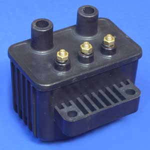
High Output Single Fire Coil P/N 2005
Ignition coil manufacturing has gone overseas to China. That is an economic reality we can’t change. What we can do differently is to be honest about it and pass the savings on to you. Right now, one factory supplies Screaming Eagle® and several of the aftermarket companies, including Crane and Dyna. Contrary to various claims, the coils are all basically the same and just differ in cosmetics. Screaming Eagle® 31746-98A (black), 31748-98A (red), and 31750-98A (orange) have a bulky connector and may not fit some stock covers. Crane and Dyna coils are packaged in a slightly smaller housing with conventional screw terminals. We contracted with another factory to build a similar coil shown above.
What if I have dual spark plug heads?
Twin Tec Model 1005, 1005S, 1006, or 1007 ignitions can be used in dual spark plug head applications. Please refer to the Dual Spark Plug Tech Note for further information.
Can I automatically retard timing with a turbocharger or nitrous oxide injection system?
Yes! This is possible with Twin Tec Model 1005, 1006, and 1007 ignitions. You will require the optional PC link cable and software. You can easily reconfigure the VOES switch input as a retard input. You can program the retard value over a 0-10° range. When the retard input is grounded, ignition timing is automatically retarded.
For a turbocharger application, you can simply replace the VOES switch with a pressure activated switch. For nitrous applications, use a relay. Connect the relay coil in parallel with the solenoid valves and use a normally open contact to ground the retard input whenever the solenoid valves are energized.
For more detailed information, please download our Turbo Boost and Nitrous Timing Retard Tech Note.
What is the VOES switch?
When is an ignition power relay recommended with single fire installations?
Some motorcycles with high compression or large displacement engines and Twin Tec Model 1005, 1005S, 1006, or 1007 single fire installations may exhibit difficult starting. The starter motor draws more current than the electrical system was originally designed for. The voltage at the battery terminals may drop to around 6 volts during cranking. The single fire coil also draws more current and an additional 1-2 volt drop may occur in the long length of wire between the battery, engine stop/run switch, and the coil. Under these conditions the voltage at the coil may be so low that the spark energy is insufficient to fire the engine. Motorcycles more than a few years old may have slightly corroded switch contacts, further aggravating the problem. The solution is to install an ignition power relay kit. The relay is controlled by the engine stop/run switch and supplies full battery voltage direct to the coil. You can order the ignition power relay kit direct from Twin Tec, or you can download the instructions and purchase a standard 12 volt automotive relay from most parts stores.
What is the VOES switch?
The VOES switch senses manifold pressure. Most carbureted H-D® models manufactured from 1980-98 and some later Sportsters® use a VOES switch to increase ignition timing advance during idle and cruise conditions. When manifold pressure (MAP) drops, the normally open VOES switch closes and connects the ignition module’s VOES input (violet/white wire) to ground. The green VOES LED will illuminate. The ignition module then uses the low MAP advance curve. If you look at the advance curves published in our instructions, you will see that the low MAP curves are somewhat more aggressive than the wide open throttle (WOT) curves. The additional advance stabilizes the idle and improves cruise fuel economy. The VOES switch has no effect on wide open throttle (WOT) operation.
During normal operation, the green VOES LED should illuminate during idle. If you have installed a high performance camshaft or made other major modifications, manifold pressure may run higher at idle. In this case, the green VOES LED will not illuminate at idle. You should still see the green VOES LED momentarily illuminate if you rev the engine up to about 2,500 RPM and then close the throttle.
We recommend that you leave the VOES switch connected. If you have a motorcycle where the VOES switch was removed, we recommend that you replace it. We offer P/N VOES-KIT-MC7. This is a complete kit with mounting bracket and has a vacuum switching level of 6-7 in-Hg that helps eliminate spark knock under light load or throttle roll-on. VOES switch instructions link.
Can I automatically retard timing with a turbocharger or nitrous oxide injection system?
Yes! This is possible with Twin Tec Model 1005, 1006, and 1007 ignitions. You will require the optional PC link cable and software. You can easily reconfigure the VOES switch input as a retard input. You can program the retard value over a 0-10° range. When the retard input is grounded, ignition timing is automatically retarded.
For a turbocharger application, you can simply replace the VOES switch with a pressure activated switch. For nitrous applications, use a relay. Connect the relay coil in parallel with the solenoid valves and use a normally open contact to ground the retard input whenever the solenoid valves are energized.
For more detailed information, please download our Turbo Boost and Nitrous Tech Note.
Several competitors’ internal (nose cone) modules have failed on my engine. Will the Twin Tec Model 1005 be more reliable?
It depends on the cause of the failure. Besides obvious physical damage, the most common causes are excessive temperature and over-voltage. If several modules have failed within a short period of time, you have to step back and try to identify the underlying cause. The following sections cover heat and over-voltage related failures.
Diagnosing and solving heat related failures.
Heat kills electronics. All the major suppliers use the same type of electronic devices rated for operation at 105 deg C (221 deg F), the highest rating available. The Model 1005 can tolerate somewhat higher temperatures, but exposure to temperatures above 125 deg C (257 deg F) will greatly reduce life expectancy. We sometimes see problematic applications where several module failures have occurred. The failure mode is a classic thermal intermittent where the module stops firing one cylinder when it gets hot. We have found that these problematic applications share one or more of the following characteristics:
- VOES switch removed or non-functional. Without vacuum advance at idle and part throttle, thermodynamic efficiency is reduced and engine temperatures increase significantly.
- Improper carburetor jetting resulting in lean air/fuel ratio (AFR). A lean AFR will cause the engine to run very hot. All performance engine modifications necessitate carburetor rejetting. Carburetors are never correctly jetted out-of-the-box. The only practical means of correctly jetting a carburetor is to test the motorcycle on a chassis dyno equipped with an exhaust gas sniffer or to use our WEGO system.
- Lack of an oil cooler on a 95 CID or larger engine.
Exhaust pipe without heat shield in close proximity to nose cone.
Model 1005 units manufactured after January, 2006 include an internal temperature sensor. These units log elapsed time in various temperature bands up to 150 deg C. You can download this data with our Operating Statistics software.
You can easily diagnose potential overheating problems by using an infrared thermometer to check the module temperature. Remove the nose cone cover and place several strips of black electrical tape on top of the module to provide a target for accurate readings (infrared thermometers will not give accurate readings from reflective surfaces). Operate the motorcycle for at least 20 minutes and take an immediate reading after shutting off the engine.
Some high output engines may be poor candidates for an internal ignition and an external module such as our Model 1007 should be considered.
Model 1005 Extreme Over-Heating Damage
My engine runs too hot for an internal ignition. How do I convert to an external module?
If you have a H-D® model and the original wire harness is still intact, you can exchange your failed ignition for our Model 1006 or Model 1007 external plug-in module as appropriate for your application. You will also require the cam timing sensor. If you no longer have it, you can purchase H-D® P/N 32400-94 from your local dealer.
If you have a custom bike or your original ignition harness has been removed, you can purchase wiring harness kit H-D® P/N 32408-90 and cam timing sensor H-D® P/N 32400-94 from your local dealer and use these items along with our Model 1006 external plug-in module. The wire color codes are the same as shown in our Model 1006 installation instructions. Please note that this wire harness kit comes with a 7 terminal connector that will only mate with the Model 1006, it cannot be used with the Model 1007.
We offer special discounted pricing for Model 1006 and Model 1007 units exchanged for failed internal ignitions, regardless of the original manufacturer. Please call us at 386-304-0700 for details.
Diagnosing and solving failures caused by electrical system over-voltage.
Failure from electrical system over-voltage causes a surge absorber inside the Model 1005 to burn up. This failure mode can be readily identified by a characteristic raised and burned area on the back side of the unit as shown in the picture below and a strong odor of burned electrical insulation.
Model 1005 Over-Voltage Damage
The most common cause of this failure is momentary disconnection of the battery while the engine is running. The system voltage then spikes up to a very high level (over 30 volts) before the voltage regulator can react. It is not unusual to also find other damaged electrical components, such as burned out light bulbs or a dead radio on touring models. The problem is generally caused by defective or loose battery cables, improper battery ground connections, or internal defects in the battery. You must correct the underlying problem before installing a new module, otherwise the same failure will occur again. We suggest the following steps:
- Replace the battery. Even new batteries can have internal defects that cause an intermittent open connection between cells when the battery is subjected to vibration or shock.
- Replace all battery cables. The battery negative terminal must make a direct connection to frame ground. Some custom motorcycles route the battery negative cable to the engine and then rely on the engine mount to make a frame ground connection. This is never acceptable.
- Temporarily replace the electronic ignition with a mechanical breaker point system. Breaker points can withstand momentary electrical overvoltage conditions without catastrophic failure. Make sure you use an appropriate 5 ohm dual fire coil. Single fire or 3 ohm coils are not compatible with breaker points.
- Check the charging system. While not the underlying cause, the voltage regulator may also have been damaged. Verify that the battery voltage doesn’t exceed 14.4 volts when the engine is running in the 2,000-3,000 RPM range.
- Operate the motorcycle for several weeks. If no other electrical failures (such as a burned out headlight) are noted, it is probably safe to install a new electronic ignition module.
What is the proper orientation for the timing rotor and Model 1005 ignition module?
This question sometimes comes up in custom applications. The Model 1005 series (including the Model 1005S EX) requires H-D® P/N 32402-83 timing rotor. This timing rotor has two slots. The Model 1005 series cannot be made to work with any other type of timing rotor. The timing rotor must rotate counterclockwise (CCW). The Model 1005 series cannot be made to work in any applications where the timing rotor rotates clockwise. Correct orientation of the timing rotor is shown in the figure below. This is a top view showing an exploded Model 1005 for reference and the orientation of the timing rotor with respect to the Hall Effect sensors when the engine is on top dead center (TDC) on the front cylinder compression stroke.
What is the difference between EX and race versions?
The new EX version of our TC88 has been given Air Resources Board Executive Order (ARB E.O.) D-641-1. This makes the TC88 EX exempt from the prohibitions of the California Vehicle Code and 50 states street legal. The maximum spark advance curve in the EX version is more conservative in the lower RPM range. The figure below compares the maximum advance curves (advance slope set to 9) at wide open throttle for the two versions.

The EX versions are suitable for all street driven applications, including large displacement and high compression engines where spark timing must be retarded from stock settings to avoid destructive engine detonation. As a compliance criteria, the Air Resources Board allows products such as the our EX versions to advance ignition timing up to 4 degrees beyond the original equipment module. Thus the maximum advance curve in the EX versions is still very aggressive and allows a performance improvement when using 92-93 octane gasoline with stock engines.
The maximum advance curve for the race versions are only suitable for true race engines where a long duration/high overlap camshaft reduces cylinder pressure in the lower RPM range and high octane race gasoline is used.
Both the EX and race versions of our ignitions have sufficient advance adjustment range for most applications using the advance slope switch settings. When used with our PC Link Evo software, both the EX and race versions allow creating a custom advance curve and no limitation exists on retarding the spark timing to solve a detonation problem which is the most common reason for creating a custom curve.
What is the difference between TC88 and TC88A ignitions?
The TC88 is for 1998-2003 carbureted Twin Cam 88® models that have an ignition module with two 12 pin connectors. The TC88A is for 2003-2004 carbureted Twin Cam 88® and Sportster® models that have an ignition module with a single 12 pin connector. Sportster® models changed from an internal ignition to the new TC88A style ignition in 2003. All 2004 carbureted Twin Cam 88® models use the new TC88A style ignition. However, H-D® appears to have also shipped a limited number of 2003 carbureted Twin Cam 88® models with the new style ignition. If you have a 2003 Twin Cam 88®, you need to check the ignition module.
The TC88A supports the J1850 data bus used on the new 2003-2004 models for communications between the ignition module, turn signal/security module (TSM/TSSM), instrument cluster, and scan tools.
What is the difference between 1998-2000 and 2001-2003 Twin Cam 88® models?
With the exception of few motorcycles manufactured in late 2003 (as explained above), the carbureted versions of all these models use an ignition module with two 12 pin connectors. H-D® did away with the camshaft position (CMP) sensor on 2001 and later models. There were reports of problems with these sensors. They may also have deleted the CMP sensor as a cost cutting measure made possible by the more sophisticated Delphi® electronics on the newer models.
Without the CMP sensor, there is no direct means of identifying which cylinder is on the compression stroke. The ignition system must use an algorithm that detects the slight reduction of crankshaft angular velocity on the compression stroke during cranking. This is not a trivial problem and not all the companies selling aftermarket ignitions have solved it.
If the ignition can’t identify the compression stroke, the system must operate in wasted spark mode. In this case, each spark plug is fired twice – once on the compression stroke and again on the exhaust stroke. This is not as bad as the old dual fire, but it’s certainly not what the designers of the Twin Cam 88® engine had in mind.
The TC88 is compatible with all 1998-2003 carbureted Twin Cam 88® models using an ignition module with two 12 pin connectors. The TC88 does not require a camshaft position sensor (CMP) and this sensor may be unplugged or removed on 1998-2000 models. If the CMP sensor fails, it may cause a short circuit that will prevent the TC88 from operating. Since the CMP sensors have a questionable history, we suggest unplugging the sensor.
Will the Twin Tec TC88 solve my hot starting problems?
Some Twin Cam 88® engines are prone to hot starting problems. When cranked after a short hot soak, the engine may “kick back.” Over time, this will cause damage to the ring gear and starter pinion.
The TC88 module uses an improved starting algorithm that includes a programmable cranking delay. The TC88 module is shipped with a zero cranking delay: it fires on the first recognized compression stroke. This works best on stock and mildly modified engines.
High compression engines may exhibit a “dieseling” phenomena after a hot soak. This can be verified by temporarily disconnecting the 3 terminal coil primary connector to disable the ignition. If the engine still kicks back or runs for several revolutions after cranking, the problem is dieseling. The only solution is to install compression releases. When compression releases are installed, best starting results will be obtained by programming the TC88 module for a 1-2 revolution cranking delay. This can be done by means of the PC Link TC88 software and optional interface cable.
What coil is recommended for use with the Twin Tec TC88 ignition?
The Twin Tec TC88 is for Twin Cam 88® engines that use an original equipment coil with .5 ohm primary resistance. You cannot use any coils with higher resistance. All available aftermarket coils for Twin Cam 88® applications, including our P/N 2008, have the same electrical characteristics as the original equipment version. Unless your original coil fails or you suspect that it has become degraded, there is no valid reason to replace it.
Does the Twin Tec TC88 support all the stock sensors on Twin Cam 88® models including the optional H-D® security system?
Yes, with the exception of the camshaft position (CMP) sensor that H-D® deleted on 2001 and later models. As explained above, we don’t require the CMP sensor.
Not all vendors support the optional H-D® security system (TSSM). The customer may be left with a false sense of security. If the motorcycle is left unlocked and the ignition system does not support the TSSM interface, the motorcycle is easily “hot-wired.”
How do I wire up a custom bike with a Twin Cam 88 Engine®?
You can easily do this with our TC88 ignition. Wire harnesses are readily available from your local H-D® dealer or Wire Plus (read further on for more details) and you can use the wiring diagram in the H-D® manual. At a minimum, you must hookup the crankshaft position (CKP) sensor, manifold pressure (MAP) sensor, ignition coil, power, and ground. If you have an early Twin Cam 88® engine with the camshaft position (CMP) sensor, you can leave this sensor disconnected.
We highly recommend that you leave the H-D® data link plug intact or buy a harness that has provision for the data link, as it is required for PC link programming. If you are not using the stock (or a Twin Cam 88® compatible) instrument cluster, leave the TC88 check engine LED output (on pin 4 of the black connector) unconnected. This signal cannot drive a lamp bulb. However, you can connect a 12 volt LED (these have an internal current limiting resistor). Suggested LED part numbers include L50151, L50261, and L50311 available from Digi-Key at www.digikey.com. These LEDs have red and white wires. Connect the red wire to switched +12 volt power and the white wire to the TC88 check engine LED output on pin 4 of the black connector.
The tach signal is at pin 12 on the black connector. The tach signal should drive most aftermarket tachs intended for H-D® applications.
If you are not using a bank sensor or TSM/TSSM module, you must ground the wire going to pin 10 on the black connector.
We supply Twin Cam wire harnesses suitable for custom applications. Note that you must ground pin 10 on the black connector (required when not using a bank sensor or TSM/TSSM module.
If you are making your own wire harness, please be advised that all the H-D® manuals and wiring diagrams show an incorrect view of the MAP sensor and mating connector. The wire colors shown for terminals A, B and C are correct but the view is reversed. If you don’t pay attention to the terminal letters engraved on the connector, your wiring harness will be incorrect and the ignition will not run. The correct view is shown below.

What is the difference between EX and race versions?
The new EX vrsion of our TC88A has been given Air Resources Board Executive Order (ARB E.O.) D-641-1. This makes the TC88A EX exempt from the prohibitions of the California Vehicle Code and 50 states street legal. The maximum spark advance curve in the EX version is more conservative in the lower RPM range. The figure below compares the maximum advance curves (advance slope set to 9) at wide open throttle for the two versions.
The EX version is suitable for all street driven applications, including large displacement and high compression engines where spark timing must be retarded from stock settings to avoid destructive engine detonation. As a compliance criteria, the Air Resources Board allows products such as the TC88A EX to advance ignition timing up to 4 degrees beyond the original equipment module. Thus the maximum advance curve in the TC88A EX is still very aggressive and allows a performance improvement when using 92-93 octane gasoline with stock engines.
The maximum advance curve for the race version is only suitable for true race engines where a long duration/high overlap camshaft reduces cylinder pressure in the lower RPM range and high octane race gasoline is used.
Both the EX and race versions of our TC88A have sufficient advance adjustment range for most applications using the advance switch settings. When used with our PC Link TC88 software, both the EX and race versions allow creating a custom advance curve and no limitation exists on retarding the spark timing to solve a detonation problem which is the most common reason for creating a custom curve.
What is the difference between TC88 and TC88A ignitions?
The TC88 is for 1998-2003 carbureted Twin Cam 88® models that have an ignition module with two 12 pin connectors. The TC88A is for 2003-2006 carbureted Twin Cam 88® and Sportster® models that have an ignition module with a single 12 pin connector. Sportster® models changed from an internal ignition to the new TC88A style ignition in 2003. All 2004 and later carbureted Twin Cam 88® models use the new TC88A style ignition. However, H-D® appears to have also shipped a limited number of 2003 carbureted Twin Cam 88® models with the new style ignition. If you have a 2003 Twin Cam 88®, you need to check the ignition module.
The TC88A supports the J1850 data bus used on 2003 and later models for communications between the ignition module, turn signal/security module (TSM/TSSM), instrument cluster, and scan tools.
What is the J1850 data bus?
The J1850 data bus is a Society of Automotive Engineers (SAE) standard. J1850 has two implementations; one used by GM/Delphi and the other by Ford. The GM/Delphi version is referred to as variable pulse width (VPW). Since H-D uses Delphi electronics, H-D® models come with this VPW version of the J1850 data bus.
J1850 is used for communications between the engine controller (ignition module or carbureted models), turn signal/security module (TSM/TSSM), instrument cluster, and scan tools. J1850 is intended for robust communications in a noisy automotive environment. The data rate is relatively slow and the J1850 bus cannot directly interface to a PC.
If the ignition module does not support the J1850 data bus, the speedometer, odometer, tachometer, and self canceling turn signals are all inoperative.
How does the TC88A communicate with a PC?
The TC88A uses same type of RS-232 serial PC link as used in our other products. RS-232 is a computer industry standard that allows use of an inexpensive cable for high speed communications. Most laptop PCs have a 9 pin D-sub connector for RS-232 communications. For those laptop PCs that lack an RS-232 port, USB or PC card adapters are readily available.
There are two reasons why we didn’t use the J1850 data bus for PC communications:
J1850 cannot directly interface to a PC. An expensive adapter, essentially a PC based scan tool, would be required. This type of adapter would cost the end user substantially more than our present PC link cable.
- J1850 is relatively slow. Our RS-232 based PC link communicates at 56 kBaud (56,000 bits/second). J1850 has a raw data rate of only 10.4 kBaud. J1850 data is organized into complex frames with a significant overhead for addressing and error detection that reduces the actual data rate to about 1/10 that of our RS-232 based PC link.
Will the TC88A solve my hot starting problems?
Some Twin Cam 88® engines are prone to hot starting problems. When cranked after a short hot soak, the engine may “kick back.” Over time, this will cause damage to the ring gear and starter pinion.
The TC88A module uses an improved starting algorithm that includes a programmable cranking delay. The TC88A module is shipped with a zero cranking delay: it fires on the first recognized compression stroke. This works best on stock and mildly modified engines.
High compression engines may exhibit a “dieseling” phenomena after a hot soak. This can be verified by temporarily disconnecting the 3 terminal coil primary connector to disable the ignition. If the engine still kicks back or runs for several revolutions after cranking, the problem is dieseling. The only solution is to install compression releases. When compression releases are installed, best starting results will be obtained by programming the TC88A module for a 1-2 revolution cranking delay. This can be done by means of the PC Link TC88 software and optional interface cable.
What coil is recommended for use with the TC88A ignition?
The TC88A is intended for applications that use an original equipment coil with .5 ohm primary resistance. You cannot use any coils with higher resistance. All available aftermarket coils for, including our P/N 2008, have the same electrical characteristics as the original equipment version. Unless your original coil fails or you suspect that it has become degraded, there is no valid reason to replace it.
Can I recalibrate the the speedometer and odometer to accommodate tire and gear changes?
Yes! This feature is a freebie with the TC88A. You don’t need to buy a separate speedometer calibrator such as the S&S unit. With the new H-D® models, the ignition module converts signal pulses from the VSS (vehicle speed sensor) to data that is transmitted to the instrument cluster. Scaling (in terms of VSS frequency/speed) varies slightly between models depending on tire size and gear ratio. You can use PC Link TC88 software to change the default scaling and recalibrate the speedometer/odometer.
How do I wire up a custom bike?
If you are building a custom bike, you can get our custom TC88A wire harness. If you use H-D® instruments intended for a J1850 application, you will not have any problems.
The TC88A was designed with custom bike applications in mind. The TC88A will operate correctly and will not set any diagnostic trouble codes if you disconnect the H-D® turn signal/security module (TSM/TSSM) or vehicle speed sensor. If you are using a custom wiring harness, you also have more flexibility as far as aftermarket instruments. You can use an aftermarket speedometer that directly interfaces to the vehicle speed sensor.
Can I use an aftermarket tachometer with the TC88A?
Yes! TC88A units with firmware revision 2.0 and higher provide an optional 12 volt square wave tach signal (one pulse per revolution) that is compatible with most tachometers intended for 1999-2003 Twin Cam 88® applications. This allows you to retrofit a wide range of tachometers to newer 2004-2006 models. Please download the TC88A installation instructions for details on tach hookup. If you plan to use the optional tach hookup, you will require the PC link cable and software to enable the tach output. TC88A units with firmware revision lower than 2.0 can be factory reprogrammed to add the tach output feature (please call for details).
Why not just connect the tachometer direct to the coil?
You will not always get an accurate RPM indication. Most aftermarket tachometers for H-D® applications can be connected directly to the ignition coil. The tachometer usually has a jumper that allows you to select one or two crank revolutions per trigger pulse for compatibility with dual and single fire ignitions. Twin Cam 88® (and 2003 and later Sportster®) engines are nominally single fire, so you can connect an aftermarket tachometer to one of the coil windings and get a correct reading – most of the time. The problem is that the ignition systems (both original equipment and aftermarket) use a complex algorithm to synchronize cylinder firing during cranking. This doesn’t always succeed. If the ignition system cannot determine which cylinder is on the compression stroke, it reverts to wasted spark mode and fires twice – once on compression and again on exhaust. Wasted spark mode rarely occurs, perhaps only once in 100 starts. However, in wasted spark mode, the tachometer will indicate twice the actual RPM.
Can the TC88A be used with new American IronHorse® motorcycles that have a crank triggered ignition?
Yes. We have a special TC88A-IH version for 2004-2007 American IronHorse® models. Please refer to the
TC88A-IH Installation Instructions
for further details. You can also download a custom advance table for modified high compression IronHorse® applications provided courtesy of Proven Performance.
Twin Tuner Series Fuel Injection and Ignition Controllers
What is the difference between the Twin Tuner and Twin Tuner II?
Both systems allow adding or subtracting fuel. The Twin Tuner II also allows you to retard spark timing up to 10 degrees.
For what applications do you recommend the Twin Tuner II?
If you are increasing the compression ratio above 10:1 or significantly increasing the engine displacement to over 100 CID, the spark advance table in the original equipment engine control module (ECM) may be too aggressive, resulting in spark knock. The Twin Tuner II allows you to retard spark timing up to 10 degrees to eliminate spark knock in these applications.
How do I select the system and initial settings best suited for my application?
Use the following flow charts to select the best system and initial settings for your application. The Twin Tuner series is appropriate for most Stage 1 (low restriction air filter and free flowing exhaust) and Stage 2 (performance camshafts) applications. For Stage 3 (increased displacement, high compression pistons, and ported heads), we recommend the Twin Tuner II series. Refer to the setup tables for initial setup recommendations.
OVERALL SELECTION FLOWCHART
TWIN TUNER SELECTION FLOWCHART
TWIN TUNER II SELECTION FLOWCHART
Download Twin Tuner Series Setup Tables
The setup tables are in the form of a PDF file and require Adobe Acrobat Reader. If you do not have Adobe Acrobat Reader installed, click on the Adobe graphic to download it for free.
Use the recommended setup table as a starting point for further tuning. If you have access to a dyno with an exhaust sniffer, refer to the following section for more guidelines. If you do not have access to a dyno, you can still make some adjustments based on the following guidelines:
1. Aftermarket camshafts will generally increase manifold pressure (reduce vacuum) near idle. The Delphi® speed-density control will compensate with excessive fuel resulting in a very rich idle. If the idle still seems rich after using the recommended settings, try further reducing the idle fuel in -5% steps.
2. If the engine still runs rough or coughs (backfire through the intake) under part throttle cruise conditions, try adding an additional 5-10% fuel in the RPM ranges where problems are noted.
3. Performance modifications will generally increase the fuel requirement at wide open throttle. If the engine still runs rough or hesitates at wide open throttle, try adding 5-10% fuel in the RPM ranges where problems are noted.
4. If throttle roll-on response is poor, try using a higher value for acceleration enrichment.
5. Twin Tuner II only. If spark knock is noted during throttle roll-on or wide open throttle, increase the ignition retard by 3 degree steps in the operating range where the spark knock was noted.
How do I tune on a dyno with an exhaust sniffer?
If you have access to a load control dyno with an exhaust sniffer, you are in a much better position to make accurate adjustments. Skip steps 1-2 for models with oxygen sensors since the original equipment engine control module (ECM) can generally make the required fuel changes at idle and part throttle cruise based on closed loop feedback from the oxygen sensors.
1. Make sure the engine is fully warmed up and has reached normal operating temperature. Run the engine at idle. Trim the idle fuel, while observing the air/fuel ratio (AFR). Idle AFR should be near 13.5. Very few applications will require adding fuel at idle. Aftermarket camshafts will generally increase manifold pressure (reduce vacuum) near idle. The Delphi® speed-density control will compensate with excessive fuel resulting in a very rich idle. If the idle AFR is still rich after using the recommended settings, try further reducing the idle fuel in -5% steps. If you are using sniffer, obtaining an accurate idle AFR reading may be difficult due to reversion effects. Reversion will result in a false lean AFR reading. If the AFR reading is above 14.6 before fuel trim, but the engine is running reasonably well, you probably have a false lean reading.
2. Run the engine at part throttle near the middle of the RPM and throttle position ranges for low and high cruise. Trim the fuel so that average AFR readings are near 13.8. If you observe a lean spot where AFR exceeds 14.6, add more fuel. You are always better off with the engine running rich in some areas than coughing in one particular lean spot.
3. Performance modifications will generally increase the fuel requirement at wide open throttle. However, it is not unusual for some 2-into-1 exhaust systems to have a torque dip at some RPM point where the engine then runs very rich and fuel must be subtracted. Do wide open throttle runs and record AFR values. Target AFR values at wide open throttle are in the 12.8-13.0 range. Make appropriate fuel trim adjustments in each RPM range. High compression engines may exhibit spark knock at wide open throttle. Spark knock can often be eliminated by adding more fuel (AFR in the 12.0-12.5 range) within the affected RPM range.
4. If throttle roll-on response is poor or a lean transient (high AFR values) is observed, try using a higher value for acceleration enrichment.
5. Twin Tuner II only. If spark knock is noted during throttle roll-on or wide open throttle, increase the ignition retard by 3 degree steps in the operating range where the spark knock was noted.
What do you recommend when tuning 2006 and later models with original equipment oxygen sensors?
If the motorcycle has Stage 1 (low restriction air filter and free flowing exhaust) or Stage 2 (mild performance camshafts) modifications, the original equipment engine control module (ECM) can generally make the required fuel changes at idle and part throttle cruise based on closed loop feedback from the oxygen sensors. The ECM will maintain the air/fuel ratio (AFR) at 14.6 during idle and part throttle cruise. You can use our Twin Tuner EX version to add fuel at wide open throttle.
When do I need to use the software and optional USB interface?
Most applications can be tuned in using the switches on the unit. In some case, such as interactions between the exhaust system and camshafts, specific RPM and throttle position ranges may need more precise fuel or spark timing adjustments and require the use of our PC Link Tuner software and our optional USB interface P/N 18014.
The Tuner Log software allows real time display of engine RPM, throttle position, and fuel and spark timing changes. The Tuner Log software is very useful for diagnosing problems, such as incorrect hookup, improper setup, or a defective throttle position sensor. You can use it to verify that the Twin Tuner/Twin Tuner II is reading correct RPM and throttle position data and that the unit is making the desired fuel and spark timing changes.
What are my options for doing advanced tuning using the PC Link Tuner software?
Start with an existing map. If you have created a map for a similar application, you can use it as a starting point for further tuning. Further tuning can be done on a dyno equipped with an exhaust sniffer or by using the Daytona Sensors Twin Scan II+ tuning aid. The Twin Scan II+ is a complete kit for engine diagnostics and tuning on Harley-Davidson® motorcycles with Delphi® fuel injection. It includes a WEGO IIID dual channel wide-band oxygen sensor system for logging front and rear cylinder air/fuel ratio (AFR) data along with engine data. Twin Scan software analyzes logged data and displays AFR and the required fuel correction (in percent) with the same RPM rows and throttle position sensor (TPS) or manifold pressure (MAP) columns used in the Twin Tuner tables. You can directly export calculated fuel correction data to Twin Tuner data files. The system can be used for tuning on a dyno or under actual riding conditions on a closed course or race track.
If you don’t have an existing map to use as a starting point, you can download the archive of setup files below. The files include zero files (with all zero values) and files corresponding to the recommendations in our flowcharts above. The archive includes a listing of files.
The setup files are in a ZIP archive file that you can download by clicking on the link above. You will require PKZIP to unzip the individual files within the archive. If you do not have PKZIP installed on your computer, you can download it from the PKWARE Inc. website.
How do I use the Twin Scan II to help tune?
You will apply the volumetric efficiency (VE) percent corrections calculated by the Twin Scan II to the Twin Tuner front and rear cylinder fuel trim tables. You are adding the calculated VE correction values from the Twin Scan II to the Twin Tuner fuel trim tables. The Twin Scan II program can directly export VE correction data to Twin Tuner data files. No manual editing is required.
1. Temporarily install the Twin Scan II wide-band exhaust gas oxygen (WEGO) sensors on the front and rear exhaust pipes.
2. Start with an available Twin Tuner setup map (file) that most closely matches your application (refer to the setup files available for download above). Use the PC Link Tuner software to upload this map to the Twin Tuner.
3. Use the Twin Scan II system to log, download, and save several sets of data under varying conditions. Use a medium data logging interval (0.5 sec) for runs at steady speeds and a short interval (0.25 sec) for runs with rapid acceleration and transients.
4. Use the Twin Scan II software to analyze the front cylinder data and print out the VE percent correction table for reference. Then use the Export to Twin Tuner command on the File menu to automatically apply the corrections to your Twin Tuner setup file.
5. Analyze the rear cylinder data and print out the VE percent correction table for reference. Then use the Export to Twin Tuner command on the File menu to automatically apply the corrections to your Twin Tuner setup file.
6. Use the PC Link Tuner software to open the modified Twin Tuner setup file and compare the printouts made in steps 4 and 5 with the front and rear cylinder fuel trim tables to verify that the values are reasonable. Remember that all VE percent correction values are added to the fuel trim tables, i.e. if a fuel trim cell was +10% before exporting data and the VE correction was +5%, the cell should now be +15%. Note that rounding of numbers may cause the final values to vary ±1%.
7. Data in decel areas (low 0-2.5% TPS above idle RPM) should be regarded with caution as exhaust reversion effects may cause errors. Unless you are experiencing a significant problem during decel, we suggest that you always leave these cells at zero percent correction.
8. Repeat steps 3-6 until no shaded cells (excessively rich or lean) appear in the VE percent correction table. Don’t worry about cells with a few percent error or minor imbalance between cylinders.
9. 2008 and later touring models with electronic throttle control. Please read the section on idle TPS offset on page 5 of the Twin Scan II instructions.
Help. I can’t get the software to communicate with the Twin Tuner.
In almost all cases, the problem is customer error caused by failure to read and follow the instructions. Common errors include:
1. Incorrect software. The only two programs you can ever use to communicate with the Twin Tuner are PC Link Tuner and Tuner Log. Check the download page on our website and verify that you the latest version. Earlier versions do not support the Twin Tuner II. If you use our Twin Scan II system for tuning, the Twin Scan II software can modify Twin Tuner files, but you must still use the PC Link Tuner software and USB interface to upload to the unit.
2. Failure to install the USB driver and configure the COM port. Follow the instructions for the USB interface. While the USB interface is plugged into your PC, use Windows Device Manager to check the COM port assignment and make sure you use the same COM port selection in our software. Once you set up the software, it will remember the COM port selection. If you later add new devices to your PC, Windows may change the original assignment.
3. Incorrect connection. Only our USB interface P/N USB-INTF can communicate with the Twin Tuner series. When used with the Twin Tuner, the USB interface connects directly to the brown wire from the Twin Tuner. An adapter is supplied with the USB interface for this purpose. The adapter also has a black wire with an alligator clip that must be connected to ground. You cannot plug the USB interface into the diagnostic connector on the motorcycle in order to communicate with the Twin Tuner. The switch on the USB interface must be in the “TC88A and all others” position. Power must be on to the Twin Tuner. This means you must turn on both the ignition key and run/stop switch. You cannot upload a tuning file after the engine has been started.
Can the Twin Tuner II be used with Buell models?
No. While the original Twin Tuner can be used with Buell models for fuel adjustments, there are some idiosyncrasies of the Buell engine control module (ECM) that prevent operation with the spark timing control circuitry of the Twin Tuner II.
What level of tech support does Daytona Twin Tec offer?
We have staff available to take tech support calls during normal business hours. If an initial telephone conversation cannot resolve the issue, we will ask you to email us the current setup file. We will try to get you a solution within 24 hours.
Please do not ask us to read you the instruction manual, lead you through basic PC or Windows operations, explain general engine tuning principles, or fax you pages from H-D® service manuals. We do offer an extensive Tech FAQ on engine tuning principles and we will gladly offer advice on specific tuning issues. From a practical standpoint, you will require broadband Internet access to download software updates and an email account to send us files for tech support purposes.
We do not offer any installation, tuning or diagnostic services at our facility. We also offer a Tech FAQ on diagnostic tools and suppliers.
Are there issues balancing fuel delivery between front and rear cylinders?
Accepted engineering practice is to use the smallest possible injectors (in terms of flow) for best control at idle and part throttle. The Delphi® style single throttle body and similar aftermarket units with siamesed runners are subject to fuel imbalance problems between the front and rear cylinders.
The Delphi® ECM synchronizes fuel injection events so that the end-of-injection for each cylinder occurs when the intake valve is starting to close. At idle and part throttle where the injector duty cycle is low, the air flow will carry the fuel into the correct cylinder. When the fuel injector duty cycle approaches 50%, fuel will start being inducted into the wrong cylinder (i.e. front injector spraying fuel while rear intake valve is still open).
The Twin Tuner, and similar competitive systems, increase fuel delivery by extending the injector pulse width. If the fuel trim is more than 10%, the fuel will continue being injected after the intake valve has already closed and this additional fuel will ultimately be carried into the opposite cylinder.
The combined effect of high injector duty cycle at wide open throttle and the extended injector pulse width make trimming fuel between cylinders difficult and somewhat unpredictable. Many customers are unfamiliar with this issue and other vendors have been reluctant to address it with any specific information or suggested techniques.
In most cases, it is best to use the same fuel trim value for both cylinders and tune based on the worst case cylinder.
If an extreme AFR imbalance exists between cylinders and a significant amount of fuel must be added to one cylinder, you can try using the injector swap on enrichment mode (Twin Tuner parameters in the PC Link Tuner software).
Why is the TCFI auto-tuning capability superior to competitive products?
Competitive systems such as the ThunderMax® and the new Dynojet® Power Vision® claim to have auto-tuning capability. Prospective customers should ask whether a given system meets two important criteria:
1. Is auto-tuning real-time and continuous? Real-time means that the system makes immediate air/fuel ratio corrections based on oxygen sensor feedback. Continuous means that the system makes corrections whenever it is running.
2. Can the user monitor, control, and override the auto-tuning corrections? Any “feedback” system using a sensor to make corrections is subject to operating regions where instabilities or errors exist.
The Thundermax® system fulfills the first criteria, it does offer real-time and continuous auto-tuning. The new Power Vision® system is neither real-time nor continuous. The user must log operating data while the engine is running, download the data to a PC, apply the air/fuel ratio corrections to a tuning file, and then reflash the engine control module (ECM) with the modified tuning file.
Only the TCFI system meets both criteria. 30 seconds after engine start, when the oxygen sensors have warmed up, the TCFI system continually updates independent front and rear cylinder air/fuel correction tables, referred to as the block learn multiplier (BLM) tables. The BLM tables have the same cells (RPM rows and throttle position columns) as the air/fuel ratio command table. Correction values are in percent units. A value less than 100% means that fuel is being taken out to correct a rich condition. A value greater than 100% mean that fuel is being added to correct a lean condition. An actual BLM table is shown below. Most of the values are between 90% to 110%, showing that the system is now well tuned and just making small corrections. The user can download the setup file from the TCFI at any time and monitor the BLM tables.
Part of the second criteria listed above is the ability to control and override the auto-tuning corrections. Only the TCFI system offers this capability on a cell-by-cell basis. You will notice cells highlighted in blue with values 0 and 1. Closed loop feedback is disabled in any BLM cells with value 0. This is useful in operating areas where exhaust reversion effects may cause incorrect sensor readings. The table has the value 0 in cells corresponding to decel (RPM above idle and closed throttle) where reversion effects are most pronounced. BLM update, but not closed loop feedback, is disabled in any BLM cells with value 1. This means that the system always starts with 100% fuel in these cells. In this table, the value 1 is used in the range of 750 to 1,500 RPM and 0% to 5% throttle position (TPS) to compensate for the unstable cold start characteristics of a particular engine combination that includes an aftermarket throttle body. Please refer to the TCFI Idle Tuning Tech Note for more information on this subject.
What is the difference between the Gen 4 and previous Gen 3 TCFI versions?
The TCFI Gen 4 is identical to the previous Gen 3 (TCFI III) version with the exception of the housing and wire harness hookup. The Gen 4 version has a lower profile housing that allows installation on Sportster® applications. For Twin-Cam applications, the WEGO IIID wide-band exhaust gas oxygen sensor interface now conveniently mounts on top of the TCFI module. The WEGO IIID wire harness has been simplified to allow easy plug-in connections for power and ground using the existing Harley-Davidson four terminal diagnostic connector.
The same setup files and software can be used interchangeably with Gen 3 and Gen 4 product versions.
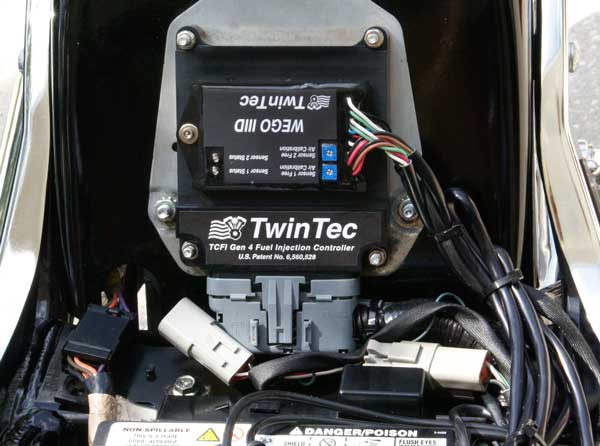
Typical TCFI Gen 4 Installation on Twin-Cam Model
What special considerations apply to 2006 and later models?
2006 and later models use a new throttle body with smaller injectors (rated 3.91 gm/sec versus 4.22 gm/sec for 2001-2005 models). The smaller injectors limit maximum power to about 90 HP. Fortunately, Screamin Eagle® offers a high performance throttle body that comes complete with larger 4.89 gm/sec injectors for under $400.
2006 Dyna® and all 2007 and later models are factory equipped with front and rear oxygen sensors. The Delphi® controller operates in closed loop under part throttle conditions. This system uses 2-wire narrow band oxygen sensors that maintain the air/fuel ratio (AFR) near 14.5. If you attempt to install an “add-on” device such as Power Commander® that changes the injector pulse width, the Delphi® system will compensate within a few miles and return to the factory programmed AFR values. The only solution is to completely replace the factory system with a unit such as our TCFI. And you won’t have to weld in oxygen sensor mounting bosses, as H-D® has already done that for you.
Does the TCFI system fully support the new 96 CID engines introduced in 2007?
Yes. Installation is very easy since the exhaust already has provision for oxygen sensors. The ECM controls the 6th gear light. The new engine requires less spark advance. We have new firmware and setup files for 2007 and later models. The TCFI does not support the active intake and exhaust used on some international models, as these are usually removed for performance applications.
Can the TCFI system be used on 2008 and later touring models with electronic throttle control?
No. Due to the integration of additional functions such as ABS brakes and cruise control along with links to the infotainment systems, replacement of the original equipment ECM would involve a level of complexity (including setup and tuning) beyond the capability of most aftermarket installers. For these models we suggest using our Twin Tuner in combination with the Twin Scan Complete kit.
Are there any special considerations that apply to the new 2007 and later models with CVO 110 CID engine?
No, the new TCFI Gen 4 fully supports the ACR system.
What is the advantage of replacing a 2007 and later ECM with your TCFI system?
All 2007 and later models use narrow-band oxygen sensors and closed loop control to maintain the AFR at 14.6 during idle and cruise. Our TCFI system with wide-band sensors allows closed loop control under all conditions including wide open throttle. You can set the AFR to any desired value from 10.5-15.0 in every RPM and throttle position cell. Other add-on systems such as the Power Commander® must either entirely disable closed loop control or restrict fuel modifications to wide open throttle cells.
What is the difference between wide-band and conventional oxygen sensors?
Conventional (narrow-band) exhaust gas oxygen sensors have been widely used in automotive applications since 1981. Conventional sensors have one to four wires and can only sense air/fuel ratio over a relatively narrow 14.5 to 15.0 range. The primary application is maintaining AFR near the 14.6-14.7 range required by catalytic converters during idle and cruise. The range of narrow-band sensors is inadequate for performance tuning. While originally developed for lab and specialized automotive applications, wide-band sensors are ideal for tuning. The 5-wire Bosch LSU 4.2 sensor used with the WEGO operates over a range of 10.3 to infinite air/fuel ratio and can be used for closed loop operation under all conditions.
For more information about wide-band oxygen sensors including the Bosch LSU 4.2, we suggest that you visit the Tech FAQ on the Daytona Sensors website at this link (click to learn about our Wideband Sensors).
How long does it take to install and tune the TCFI for a typical application?
The TCFI is a simple plug-in that will take about 15 minutes to install. On 2001-2006 models, you can expect to spend about 2-3 hours installing the WEGO sensors as this requires exhaust removal and welding of mounting nuts for the oxygen sensor. Starting with the 2007 models, the WEGO sensors fit in place of the stock narrow-band sensors. Initial tuning of the TCFI will probably take about 1-2 hours, with another hour spent doing final checks after the customer has logged some time on the system. If you are doing your first installation, you will need some time to familiarize yourself with the system. If you encounter problems with an aftermarket throttle body or wiring issues on a custom bike, additional time may be required to complete the installation.
What skills and resources do I need to successfully install and tune this system?
You need to make a realistic assessment of your skill level. We have encountered issues with customers that simply lacked the requisite PC literacy and resources to be successful with the TCFI. If you have never worked with H-D® EFI systems, the TCFI is not the place to start. Tuning the TCFI requires competency in PC operation, using Microsoft Windows based programs, and basic engine tuning and fuel injection mapping concepts. The TCFI installer is assumed to be familiar with the Delphi® fuel injection system and to have access to basic test equipment and factory service manuals. We suggest that you download the TCFI Installation & Tuning Manual, study it, and make sure you feel comfortable with it before purchasing the TCFI system.
If you have experience with the Screamin Eagle® Race Tuner (SERT), you should have no difficulty transitioning to the TCFI. From a software standpoint, the SERT Tuning Mode corresponds to our PC Link TCFI and the SERT Data Mode corresponds to our TCFI Log.
Our tech support is limited to TCFI and engine tuning issues. We cannot provide tech support for PC or Windows related issues. You need broadband Internet access to download software and firmware updates and an email account to send us files for tech support purposes. You will also require a program such as PKZIP or WinZIP to archive files prior to attaching to an email.
One often overlooked resource is time. When you are first starting with the TCFI, you will probably require 1-2 hours to read the instructions and practice with the software.
Can the TCFI be made to work with every possible combination of engine parts?
Mixing engine parts from several different vendors involves some risk. Sometimes you get very lucky and come up with a combination that wins the dyno shootout, most of the time the system can be tuned to give good performance and drivability, but on a few rare occasions it just can’t be made to work. At this point in time, the industry doesn’t have enough of a knowledge base to accurately predict what parts will or will not work together. The problem has been around for years, but was masked by the forgiving nature of carburetors. Sloppy engine building techniques such as not bothering to CC heads and calculate the compression ratio or selecting parts for cosmetic appeal compounds the risk.
What level of tech support does Daytona Twin Tec offer?
We have staff available to take tech support calls during normal business hours. If an initial telephone conversation cannot resolve the issue, we will ask you to email us the current setup file and a data logging file exhibiting the problem. We will try to get you a solution within 24 hours.
Please do not ask us to read you the instruction manual, lead you through basic PC or Windows operations, or fax you pages from H-D® service manuals. We do offer an extensive Tech FAQ on engine tuning principles and we will gladly offer advice on specific tuning issues.
Most tech support calls involve tuning issues that can easily be resolved. A small percentage of applications have underlying mechanical or parts compatibility issues that cannot be resolved by tuning alone. The most common issues encountered include inappropriate exhaust systems, mechanical/thermal problems with aftermarket or modified throttle bodies, and inadequate starting systems for high compression engines.
We do not offer any installation, tuning or diagnostic services at our facility.
Can you recommend some books that cover basic automotive electronics and engine control systems?
We have listed a few suggested volumes that are available at Amazon (www.amazon.com):
Understanding Automotive Electronics (Sixth Edition) by W. B. Ribbens (highly recommended – covers control system theory)
Automotive Fuel and Emissions Control Systems by J. D. Halderman (used by many community colleges for ASE certification programs – much of the material is directly applicable to motorcycle EFI systems)
How to Tune and Modify Engine Management Systems by J. Hartman (automotive oriented – material in first 15 chapters is generally applicable to motorcycle EFI systems).
What is the difference between speed-density and alpha-N fuel injection control systems?
The OE Delphi® system is a speed-density control system. It remains a speed-density control system even when devices such as the RevTech DFO, Dynojet® Power Commander®, or Screamin Eagle® Race Tuner are added. The TCFI is an alpha-N control system.
Speed-density control calculates air flow (and consequently meters the correct amount of fuel to attain the desired air/fuel ratio) based on engine RPM (the speed term) and manifold pressure and temperature (the air density term). Once calibrated, speed-density systems can accurately meter fuel as long as the manifold pressure is well behaved. Speed-density system are somewhat forgiving for minor vacuum leaks and inconsistent throttle body behavior. However, speed-density control cannot cope with the erratic manifold pressure characteristic of long duration, high overlap camshafts.
Alpha-N systems are typically used in racing applications where the camshaft characteristics preclude speed-density control. Alpha-N control calculates airflow based on throttle angle (the alpha term) and engine RPM (the N term). In addition, most alpha-N systems make a correction based on air temperature. The accuracy of an alpha-N system is highly dependent on consistent throttle body behavior and is adversely affected by any vacuum leaks. Adding closed loop feedback from a wideband exhaust gas oxygen sensor greatly improves the accuracy of an alpha-N system. The major advantage is that alpha-N control has no dependence on manifold pressure and is able to tolerate radical camshaft profiles.
Speed-density versions of the TCFI are available for special applications where alpha-N control is not suitable, such as motorcycles with turbo or supercharger installations.
What is the difference between open loop and closed loop fuel control?
Simplified block diagrams for engine control modules with open and closed loop fuel control are shown above. The open loop system has inputs for RPM, throttle position (TPS), and cold start related variables (such as engine temperature and elapsed time since engine start). Fuel lookup tables translate these inputs into a predetermined fuel injector pulse width. The fuel injectors then deliver fuel to the engine. The overall accuracy of the system is dependent on the lookup tables and the fuel injectors. If the lookup tables are not correct or the fuel injectors become clogged with deposits over time, engine operation will suffer.
With a closed loop fuel control system, a feedback path is added to allow the system to make corrections. In the case of the TCFI system, wide-band oxygen sensors measure the actual engine air/fuel ratio (AFR). The system compares the AFR command from the fuel tables to the measured AFR from the sensors. The difference between the AFR command and the measured AFR is referred to as the AFR error. The system slowly makes corrections to the injector pulse width to drive this AFR error to zero. These corrections are stored in a block learn multiplier (BLM) table organized into RPM and TPS cells. The BLM table is continually updated. When engine operation shifts to a new cell (for example the RPM changes), the system can use the BLM value last saved in this cell as a starting point for further corrections. Over time, the system will learn the BLM value required for every cell in order to drive the AFR error to zero. This process is referred to as auto-tuning. With the use of wide-band sensors, closed loop control is possible throughout the range of 10.5-15.0 AFR.
The 2007 and later Delphi® systems are similar, except that they use narrow-band oxygen sensors that limit closed loop fuel control to 14.6 AFR. H-D® uses the terminology “error integrator” in place of BLM.
The block diagram above shows how closed loop fuel control is implemented in the TCFI. An initial estimate of horsepower and injector size (flow rate) is used to calculate a base injector pulse width. Base injector pulse width corresponds to the amount of fuel required to generate a stoichiometric mixture (14.7 AFR) at wide open throttle (WOT), 6,000 RPM and standard atmospheric conditions. Base injector pulse width then corrected for intake air temperature (IAT) and barometric pressure. At any given RPM and throttle position (TPS), the corrected base injector pulse width is multiplied by the values in the Alpha-N table (main fuel table), AFR table (the AFR command), front cylinder trim table (only for the front cylinder), and block learn multiplier (BLM) tables. The BLM tables store closed loop correction factors based on feedback from the WEGO system. Independent BLM tables are used for front and rear cylinders. The BLM tables are continually updated whenever the system is operating in closed loop (generally 30 seconds after engine start). The BLM tables are updated based on the AFR error (difference between AFR command and actual AFR read by the WEGO system). Additional cold start enrichment fuel is applied based on engine temperature and elapsed time since engine start. Priming fuel is injected when the run/stop switch is cycled on. A fixed pulse width injection is also used during cranking (RPM < 400). Two tables set the priming and cranking pulse widths based on engine temperature. Separate control loops are used for the front and rear cylinders.
How does the block learn multiplier (BLM) value respond to AFR changes?
The figure above shows how a closed loop fuel control system such as the TCFI responds to a disturbance. AFR is the air/fuel ratio measured by a wide-band oxygen sensor. The measured AFR value is initially equal to the AFR command (zero error) and the BLM value is 100% (no fuel correction). A disturbance reduces the measured AFR to about 12.5. The system responds by lowering the BLM value to remove excess fuel and thus reduce the AFR error. After several seconds, the error is again zero with measured AFR equal to the AFR command.
How does the TCFI closed loop idle speed control work?
The output of the idle RPM control loop is idle air control (IAC) stepper motor position ranging from 0-127. A higher IAC value allows more air flow and increases engine RPM. A table sets the idle RPM command as a function of engine temperature. This allows a higher idle RPM while the engine is cold. Closed loop idle RPM control is only enabled when vehicle speed is zero and TPS is less than the idle TPS value (usually 1%). Under open loop conditions (such as the motorcycle being driven while the engine is warming up), IAC position is continually adjusted based on engine temperature and elapsed time since engine start. When the engine is fully warmed up, the system assumes that the IAC position will be close to a nominal value (usually 30). Additional idle air (IAC > nominal IAC value) is considered the same as increasing TPS since the effect on airflow is identical. Under cold start conditions, when the IAC value is high, the system may be using the 2.5% or 5% TPS rows in the fuel tables even when the throttle is closed.
Do I need a load control dyno with exhaust sniffer?
Regardless of what some people may claim, it is impossible to properly tune a fuel injection system on a modified engine without some means of covering the entire engine load range (from decel to wide open throttle) and exhaust gas analysis. If you use a system like the Dynojet® Power Commande®, you had better find a shop with the DynoJet® Model 250 load control dyno and optional air/fuel ratio monitor.
You can accomplish the same result with the TCFI and WEGO by simply riding the bike for several hours. As you run through different engine loads and RPM levels, the system auto-tunes the fuel tables.
What applications has the TCFI been tested with?
We have tested and qualified the TCFI with engines up to 145 CID capable of producing 170 HP. With a dual independent runner throttle body and 6.0 gm/sec injectors, the TCFI can support engines up to about 195 HP.
How do I set up and tune the TCFI for a particular application?
We provide setup files for common applications based on using the WEGO for auto-tuning fuel tables. We suggest that you download the TCFI Installation & Tuning Manual for more details.
Do I need to spend time on a dyno?
Auto-tuning under actual riding conditions with the WEGO generally gives better results because the operating conditions are more realistic. Do the auto-tuning first. Then, if you want to get maximum horsepower at wide open throttle, do dyno runs to fine tune the ignition advance and air/fuel ratio.
What are the limitations of the stock throttle body?
The stock throttle body is inadequate for performance engines and will not flow sufficient air above 4500 RPM. Maximum power will be limited to about 105 HP (injector flow rating may impose an even lower limit). Our tests have shown that boring out the stock throttle body is ineffective. An aftermarket throttle body greater than 50mm is required for maximum power. The stock air cleaner is grossly restrictive and must always be replaced for any performance application.
You can easily verify air flow restrictions with the TCFI Log data logging software. Examine manifold pressure (MAP) at wide open throttle. If MAP drops off as RPM increases, you know you have a problem.
What aftermarket throttle bodies have been tested with the TCFI?
Aftermarket throttle bodies fall into two categories: single throttle body with siamesed runner (same configuration as the stock Delphi®) and dual independent runner. We have tested the 53mm single throttle body system from Horsepower Inc. We have also tested the S&S Cycle VFI Tuned Induction that is a dual independent runner configuration. There was no measurable difference in performance at high RPM and wide open throttle between any of these systems on our 95 CID engine. However, part throttle operation between 1500 and 3000 RPM was smoother with the dual independent runner system.
When a dual independent runner intake is combined with a dual independent exhaust (no crossover or 2-into-1 collector), the V-twin engine now operates as if it were two single cylinder engines. Problems with fuel distribution between cylinders, normally aggravated by the odd 315° and 405° firing intervals, are almost entirely eliminated. This greatly reduces the potential for tuning headaches.
What issues have been encountered with aftermarket or modified throttle bodies?
You must budget some time to properly adjust the idle TPS setting and idle stop. Throttle blade, linkage or cable binding are often encountered with installation of an aftermarket throttle body. Our customers have also encountered thermal problems, where a mismatch in thermal expansion between the throttle blade and throttle body results in idle instability as the engine heat up. Improper installation or faulty throttle shaft seals can cause intermittent vacuum leaks that are difficult to diagnose. Note: please refer to the section on idle air control (IAC) actuator issues when changing throttle bodies on 2006 and later models.
Will the exhaust system affect the TCFI?
Yes. The choice of exhaust system has a very significant effect. Unfortunately, many exhaust systems have been designed without any consideration of gas flow dynamics. This is true of both OE and aftermarket systems. The worst example is the OE exhaust used on “bagger” style motorcycles, where two pipes split off near the rear cylinder and then run to each side of the bike. At part throttle, air is actually sucked into the left tailpipe, wreaking havoc with oxygen sensor readings. The only solution is to install a true dual type performance exhaust.
Our customers have reported that some aftermarket 2-into-1 systems, such as the Thunderheader can cause significant tuning headaches, whereas others such as the Supertrapp, Vance & Hines Pro Pipe and White Brothers E-series seem trouble free. The problem with the Thunderheader appears to be over-scavenging around 2500 RPM with some camshaft combinations. Customers have reported that bending the ends of the so called “flow director” to increase backpressure at low RPM appears to help.
WARNING: If you can insert a broomstick through the mufflers, you have the equivalent of open drag pipes and the WEGO sensors will not read accurate AFR values except at wide open throttle.
Please note that if you use drag pipes or other open pipes, auto-tuning may not be possible at idle or part throttle due to reversion effects. In this case, you have three options:
1. Modify the exhaust to allow auto-tuning at idle and part throttle by adding a restriction such as the washers shown in the figure below or some other type of baffling. For race applications, you can remove the restriction after auto-tuning the idle and part throttle cells and then lock out closed loop operation by using the special value 0 in the BLM tables for these cells.
2. Use a rubber hose to extend the exhaust length during auto-tuning at idle and part throttle. For more information, please contact our tech support.
3. Manually tune the fuel tables for idle and part throttle cells. This involves trial and error and is not recommended. Closed loop operation in idle and part throttle cells must be locked out by using the special value 0 in the BLM tables for the affected cells. Use washers with an OD that is 2/3 to 3/4 the ID of the pipe (for example, 1-1/2” OD washers are suitable for pipes with an ID of 2” to 2.25”). Weld ¼-20 socket head cap screws to the washers as shown. Drill holes at the bottom of the pipes about 2” from the end and use decorative acorn nuts to secure the washer assemblies. We suggest that you use stainless steel hardware.
The washers will reflect positive pressure waves that will cancel out the negative pressure waves reflecting from the end of the pipes. You can turn the washers just like throttle blades to provide more or less restriction. Dyno tests will show a significant increase in midrange torque and a small drop in top end horsepower as the restriction is increased.
What is the effect of an open exhaust on torque and horsepower?
Harley-Davidson® engine tuners have known for years that while open drag pipes may make the most power at high RPM, some exhaust back pressure is required for maximum torque in the low to mid RPM range. Some years back, we ran dyno tests on a 2003 Fat Boy with a 95 CID engine and our TCFI system. The exhaust system consisted of stock headers and Cycle Shack slip-on mufflers without a crossover. Two dyno runs are shown in the figure below. Dyno run 10 (red) is with the Cycle Shack muffler inserts removed, resulting in the equivalent of open drag pipes. Dyno run 9 (blue) is with 1-1/2″ washers installed near the end of the pipes as described in the preceding section. At 3,500 RPM the engine gained more than 10 ft-lbs torque with the washers installed to provide some back pressure. At 5,800 RPM the engine gained almost 7 HP with the open pipes. On the street, the bike felt much faster with the 12% additional torque available when the washers were installed.
Should the WEGO be left hooked up?
Yes! Due to the inherent limitations of sensing airflow by measuring throttle angle, Alpha-N fuel injection systems cannot precisely control air/fuel ratio without feedback from a wide-band sensor system. The TCFI is not intended to be used without the WEGO.
Can the TCFI solve starting problems with high compression engines?
Probably not. We have also encountered cases where the customer failed to CC the cylinder heads and calculate the actual compression ratio – only to later discover that it is much higher than expected. The stock starting system is inadequate for high displacement, high compression engines. For these applications, you must install compression releases and upgrade the starter, ring gear/pinion, and battery. Based on customer feedback, the best available starting system is the combination of a Tech Cycle 2.0 KW Tornado starter, Rivera Engineering 84 tooth ring gear/pinion set, and Yuasa YuMicron CX battery.
How do you select the proper size fuel injectors?
Single throttle body siamesed runner systems usually require some tuning effort to balance fuel delivery between the front and rear cylinder at part throttle. Fuel imbalance problems become worse with more camshaft overlap/duration and with low exhaust back pressure. Fuel injector duty cycle limitations must also be considered. The industry is just starting to recognize the extent of this issue. If fuel cannot be delivered to the correct cylinder, the trimming process will not be successful.
Accepted engineering practice is to use the smallest possible injectors (in terms of flow) for best control at idle and part throttle. When fuel injector duty cycle exceeds 50% in a system with siamesed runners, fuel will be inducted into the wrong cylinder. For example, at high duty cycle, the front injector will be spraying fuel while the rear intake valve is still open. The TCFI cannot correct this problem.
Dual independent runner systems do not suffer from this type of fuel imbalance problem and the fuel injectors may be run upwards of 80% duty cycle. At high duty cycles, fuel may puddle up in front of the intake valve but will ultimately be inducted into the correct cylinder. Stock Delphi® injectors are rated at 3.91 or 4.22 gm/sec flow depending on model year. We offer larger injectors for most Harley Models visit our injector link. The following table lists conservative rear wheel horsepower limits based on injector size and type of throttle body.
Injector Size | Siamesed Runners | Dual Independent Runners |
3.91 gm/sec (stock 2006-2010 P/N 27709-06A) | 90 HP | Not available |
4.22 gm/sec (stock 2001-2005) | 100 HP | 135 HP |
4.89 gm/sec (2006 Screamin Eagle® P/N 27654-06) | 110 HP | Not available |
6.0 gm/sec | 130 HP | 195 HP |
If you significantly exceed these recommendations, it may not be possible to balance fuel between front and rear cylinders. The result may be a lean cylinder and possible engine damage at high RPM wide open throttle.
On a final note, the S&S Cycle VFI Tuned Induction is supplied with appropriately sized fuel injectors that will support engines up to 150 HP.
Why is limiting the injector duty cycle so important?

How are injector requirements calculated?
The math is relatively simple.
Injector flow = (HP x BSFC) / (Number of Injectors x Duty Cycle)
Where:
Injector flow is in units of lbs/hour
HP is maximum engine horsepower
BSFC is brake specific fuel consumption (assumed to be 0.45 to 0.50 lbs/HP-hour)
Number of Injectors is always 2 for a V twin type engine
Duty Cycle is 0.8 (80%) – the accepted industry standard (injector flow does not increase appreciably above 80-85% duty cycle)
For example, a 135 HP engine with 0.45 BSFC, two injectors, and 80% maximum duty cycle will require injectors flowing:
(135 x 0.45) / (2 x 0.8) = 38 lbs/hour
Injectors are commonly rated for flow at 43.5 psi (about 3 bar). The injector flow rating must be corrected based on the actual operating pressure. The Delphi® system runs at approximately 58 psi. Flow varies as the square root of the pressure:
Rated Flow = Required Flow x √(Rated Pressure / Actual Pressure)
For our example, the injectors should have a nominal rating of:
38 x √(43.5 / 58) = 32.9 lbs/hour (at 43.5 psi)
Some companies rate injectors in lbs/hour, Delphi uses a metric rating of gm/sec. The appropriate conversion constant is 1 gm/sec = 7.93 lb/hour.
Back to our example, we would require injectors with a metric rating of:
32.9 / 7.93 = 4.14 gm/sec
The 2001-2005 model year stock injectors rated at approximately 4.2 gm/sec would be adequate for this application.
You can use our fuel injector calculator to estimate your injector requirements. Use a BSFC of 0.45 for normally aspirated engines and 0.60 for turbocharged or supercharged engines. You can use a maximum duty cycle of 80% for most applications, but remember that fuel imbalance can occur in siamesed runner intakes when the duty cycle exceeds 50%. Use the default value of 43.5 psi for injector rated pressure. Unless you have changed the fuel pressure regulator, use the value of 58 psi for the actual system pressure. The calculator below will show the required injector flow rating in the three most common units. Note that the calculation is based on engine horsepower. Increase expected rear wheel horsepower figures (as would be measured on a chassis dyno) by 10-15% to arrive at engine horsepower. TCFI and Screamin Eagle® Race Tuner (SERT) systems require input of injector flow rate in gm/sec at the system operating pressure. If you have an injector rated in a different unit or at some other pressure, you can use the conversion calculator below.
Are there known issues with the injectors on 2006 H-D® models?
H-D® has issued Service Bulletin M-1185. Most 2006 models have narrow 8° spray pattern injectors (P/N 27625-06) that cause poor cold start, idle, and cruise. The replacement injectors (P/N 27709-06A) have a 25° spray pattern. You must verify that the injectors have been replaced. The TCFI will not operate correctly with the original injectors.
What injectors and throttle bodies are available for 2006 and later models?
The injectors and throttle body changed in 2006. P/N 27709-06A stock injectors are rated at 3.9 gm/sec – less than the 4.2 gm/sec parts used in 2001-2005. Screamin Eagle® P/N 27654-06 injectors rated at 4.9 gm/sec are recommended for performance applications. For applications over 100 HP, the 50mm Screamin Eagle® throttle body (P/N 27623-05) is an unbeatable deal.
Can the new Screamin Eagle® 50mm throttle body be used on earlier models?
The 50mm Screamin Eagle® throttle body (P/N 27623-05) has slightly larger port diameters and is intended to be used with matching Screamin Eagle® heads or modified heads. Kuryakyn offers adapter flanges (P/N 457) that allow using the Screamin Eagle® throttle body on earlier heads. However, if you use the throttle body on 2001-2005 models, you must rewire the idle air control (IAC) connector (see details in following section).
Is there an issue with the idle air control (IAC) actuator when changing throttle bodies?
The IAC actuator and wire harness connections changed on 2006 and later models. If you install an aftermarket throttle body on 2006 and later models and reuse the original equipment IAC actuator, you will not encounter any problems. If the aftermarket throttle body requires the earlier style actuator, you must swap the wires going to pins A and C. If you install the new 50mm Screamin’ Eagle® throttle body (P/N 27623-05) on a 2001-2005 model, you must swap the wires going to pins A and C on the IAC actuator. Incorrect IAC connections will cause idle speed control to fail. This will result in erratic engine operation and the ECM setting IAC related diagnostic codes.
Can the TCFI be adapted to work on bikes with the older Marelli fuel injection system?
A conversion harness that allows TCFI installation on Twin-Cam 88® engines with the Marelli fuel injection is available from Thayer Sales (585-762-4705). Please contact Thayer Sales for details. The TCFI cannot be adapted to earlier Evolution® engines as these lack a crank trigger.
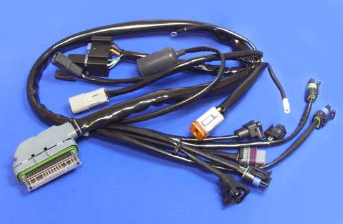
TCFI Conversion Harness for Marelli Fuel Injection
Will the TCFI work with the fuel injection used on new Buell® models?
No, the TCFI is specifically intended for use with 2001 and later H-D® models with the Delphi® ECM. The Delphi® ECM has a 36 pin connector. Newer Buell® models use a small ECM with two 12 pin Deutsch connectors. Check out our Twin Tuner for Buell® models.
Can I use the TCFI on a custom motorcycle?
If you start out with a fuel injected Twin-Cam engine, you should not encounter any problems. You must retain all the original equipment sensors and actuators. Two areas that are often overlooked are the instrument cluster and turn signals. Like the stock Delphi® ECM, the TCFI requires a vehicle speed sensor (VSS) signal. If you are using an aftermarket instrument cluster, you can connect the VSS sensor directly to the TCFI. With the TCFI, you can eliminate the stock turn signal/security module (TSM/TSSM) and use any aftermarket turn signal controller. The Marelli conversion harness shown above can also be used as an engine wiring harness for TCFI installations on custom bikes.
How can an aftermarket tachometer or shift light be connected to the TCFI?
The Delphi® ECM and TCFI both have a tach signal available on pin 3 of the 36 pin ECM connector. This is a one pulse per revolution (PPR) 12 volt square wave signal with 50% duty cycle that is compatible with all standard tachometers and other RPM activated accessories such as shift lights. 2004 and later models use the J1850 data bus for communication with original equipment tachometers, however the tach signal on pin 3 can still be used if you are installing an earlier style H-D® or aftermarket tach.
How can an aftermarket speedometer be installed on 2004 and later models?
2001-2003 models have the vehicle speed sensor (VSS) connected to the speedometer. A VSS signal is routed from the speedometer to pin 33 on the 36 pin ECM connector. The J1850 data bus is used to send distance data to the turn signal/security module (TSM/TSSM) for turn signal cancellation. On 2004 and later models, the VSS is connected direct to pin 33 on the ECM. Speed and distance data is sent on the J1850 data bus to the speedometer and TSM/TSSM.
For all model years, the ECM requires a valid VSS signal for idle RPM control and turn signal cancellation. If you plan to install an aftermarket speedometer, you must maintain the VSS signal to the ECM. For 2004 and later models, you can try connecting the VSS input on the aftermarket speedometer to the existing VSS signal on pin 33 (leave the existing VSS ground and power connections undisturbed). After completing the hookup, you should test drive the motorcycle, download data with TCFI Log software, check VSS data, and verify that the ECM is still receiving a valid VSS signal. If the speedometer does not function with this hookup, it is not compatible with a fuel injected application.
Why is the VRFI auto-tuning capability superior to competitive products?
Competitive systems such as the ThunderMax® and the new Dynojet® Power Vision® claim to have auto-tuning capability. Prospective customers should ask whether a given system meets two important criteria:
1. Is auto-tuning real-time and continuous? Real-time means that the system makes immediate air/fuel ratio corrections based on oxygen sensor feedback. Continuous means that the system makes corrections whenever it is running.
2. Can the user monitor, control, and override the auto-tuning corrections? Any “feedback” system using a sensor to make corrections is subject to operating regions where instabilities or errors exist.
The Thundermax® system fulfills the first criteria, it does offer real-time and continuous auto-tuning. The new Power Vision® system is neither real-time nor continuous. The user must log operating data while the engine is running, download the data to a PC, apply the air/fuel ratio corrections to a tuning file, and then reflash the engine control module (ECM) with the modified tuning file.
Only the VRFI system meets both criteria. 30 seconds after engine start, when the oxygen sensors have warmed up, the VRFI system continually updates independent front and rear cylinder air/fuel correction tables, referred to as the block learn multiplier (BLM) tables. The BLM tables have the same cells (RPM rows and throttle position columns) as the air/fuel ratio command table. Correction values are in percent units. A value less than 100% means that fuel is being taken out to correct a rich condition. A value greater than 100% mean that fuel is being added to correct a lean condition. An actual BLM table is shown below (the table is from our Twin-Cam TCFI system, but the VRFI functions the same). Most of the values are between 90% to 110%, showing that the system is now well tuned and just making small corrections. The user can download the setup file from the VRFI at any time and monitor the BLM tables.
Part of the second criteria listed above is the ability to control and override the auto-tuning corrections. Only the VRFI system offers this capability on a cell-by-cell basis. You will notice cells highlighted in blue with values 0 and 1. Closed loop feedback is disabled in any BLM cells with value 0. This is useful in operating areas where exhaust reversion effects may cause incorrect sensor readings. The table has the value 0 in cells corresponding to decel (RPM above idle and closed throttle) where reversion effects are most pronounced. BLM update, but not closed loop feedback, is disabled in any BLM cells with value 1. This means that the system always starts with 100% fuel in these cells. In this table, the value 1 is used in the range of 750 to 1,500 RPM and 0% to 5% throttle position (TPS) to compensate for the unstable cold start characteristics of a particular engine combination that includes an aftermarket throttle body. Please refer to the TCFI Idle Tuning Tech Note for more information on this subject (basic operation of the VRFI is the same as our Twin-Cam TCFI system).
What is the advantage of the new VRFI system with dual channel WEGO?
The new system with front and rear wide-band exhaust gas oxygen sensors allows a substantial reduction in tuning effort compared to our earlier single sensor units. The tedious operation of moving the single sensor from cylinder to cylinder during the tuning process is completely eliminated. Auto-tuning is also extended into the idle RPM range, further reducing the tuning effort. The new system is also more tolerant of throttle body and throttle position sensor variations. Closed loop operation occurs within 30 seconds even if the engine is cold.
For what applications do you recommend the VRFI?
The VRFI is intended for high performance race engines. Please note that the VRFI controller cannot be used as a replacement for a failed Delphi® module.
How long does it take to install and tune the VRFI for a typical application?
The VRFI is a simple plug-in that will take about 10-15 minutes to install. You can expect to spend about 3-4 hours installing the WEGO as this requires exhaust removal and welding of mounting nuts for the oxygen sensor. Initial tuning of the VRFI will probably take 2-3 hours, with another hour spent doing final checks after the customer has logged some time on the system. If you are doing your first installation, you should plan on spending several days familiarizing yourself with the system. If you encounter problems with an aftermarket performance items, substantial additional time may be required to complete the installation.
What skills and resources do I need to successfully install and tune this system?
You need to make a realistic assessment of your skill level. We have encountered issues with customers that simply lacked the requisite PC literacy and resources to be successful with the VRFI. If you have never worked with H-D® EFI systems, the VRFI is not the place to start. Tuning the VRFI requires competency in PC operation, using Microsoft Windows based programs, and basic engine tuning and fuel injection mapping concepts including the use of an exhaust gas analyzer to monitor AFR (air/fuel ratio). The VRFI installer is assumed to be familiar with the Delphi® fuel injection system and to have access to basic test equipment and factory service manuals. We suggest that you download the VRFI Installation and Tuning Manual, study it, and make sure you feel comfortable with it before purchasing the VRFI system.
Our tech support is limited to VRFI and engine tuning issues. We cannot provide tech support for PC or Windows related issues. Please do not ask us to explain how to use a mouse, open/close files, copy files to disk, organize folders, or other basic Windows or PC operations. From a practical standpoint, you will require broadband Internet access to download software and firmware updates and an email account to send us files for tech support purposes. You will also require a program such as PKZIP or WinZIP to archive files prior to attaching to an email.
What level of tech support does Daytona Twin Tec offer?
We have staff available to take tech support calls during normal business hours. If an initial telephone conversation cannot resolve the issue, we will ask you to email us the current setup file and a data logging file exhibiting the problem. We will try to get you a solution within 24 hours.
Please do not ask us to read you the instruction manual, lead you through basic PC or Windows operations, explain general engine tuning principles, or fax you pages from H-D® service manuals.
Most tech support calls involve tuning issues that can easily be resolved. A small percentage of applications have underlying mechanical or parts compatibility issues that cannot be resolved by tuning alone. The most common issues encountered include mechanical/thermal problems with aftermarket or modified throttle bodies, inappropriate exhaust systems, and inadequate starting systems for high compression engines.
We do not offer any installation, tuning or diagnostic services at our facility.
What is the difference between the VRFI and TCFI?
The two systems are very similar. If you have used one of our TCFI systems, you will quickly become very familiar with the VRFI. All the basic functions of the two units and the accompanying software are the same, except that the VRFI has slightly different electronics and firmware to support the unique characteristics of the VRSC engine.
You cannot swap the two units or reprogram the firmware to change a TCFI to VRFI or vice versa.
What is the difference between speed-density and alpha-N fuel injection control systems?
The OE Delphi® system is a speed-density control system. It remains a speed-density control system even when devices such as the RevTech DFO, Dynojet Power Commander, or Screaming Eagle EFI Tuner are added. The VRFI is an alpha-N control system.
Speed-density control calculates air flow (and consequently meters the correct amount of fuel to attain the desired air/fuel ratio) based on engine RPM (the speed term) and manifold pressure and temperature (the air density term). Once calibrated, speed-density systems can accurately meter fuel as long as the manifold pressure is well behaved. Speed-density system are somewhat forgiving for minor vacuum leaks and inconsistent throttle body behavior. However, speed-density control cannot cope with the erratic manifold pressure characteristic of long duration, high overlap camshafts.
Alpha-N systems are typically used in racing applications where the camshaft characteristics preclude speed-density control. Alpha-N control calculates airflow based on throttle angle (the alpha term) and engine RPM (the N term). In addition, most alpha-N systems make a correction based on air temperature. The accuracy of an alpha-N system is highly dependent on consistent throttle body behavior and is adversely affected by any vacuum leaks. Adding closed loop feedback from a wideband exhaust gas oxygen sensor greatly improves the accuracy of an alpha-N system. The major advantage is that alpha-N control has no dependence on manifold pressure and is able to tolerate radical camshaft profiles.
Do I need a load control dyno with exhaust sniffer?
Regardless of what some people may claim, it is impossible to properly tune a fuel injection system on a modified engine without some means of covering the entire engine load range (from decel to wide open throttle) and exhaust gas analysis. If you use a system like the Dynojet Power Commander IIIr, you had better find a shop with the DynoJet Model 250 load control dyno and optional air/fuel ratio monitor.
You can accomplish the same result with the VRFI and WEGO by simply riding the bike for several hours. As you run through different engine loads and RPM levels, the system auto-tunes the fuel tables.
How do I set up and tune the VRFI for a particular application?
We provide setup files for common applications based on using the WEGO for auto-tuning fuel tables. Some tweaking of idle fuel and ignition advance is generally required. We suggest that you download the VRFI Installation and Tuning Manual for more details.
Do I need to spend time on a dyno?
Auto-tuning under actual riding conditions with the WEGO generally gives better results because the operating conditions are more realistic. Do the auto-tuning first. Then, if you want to get maximum horsepower at wide open throttle, do dyno runs to fine tune the ignition advance and air/fuel ratio.
Will the exhaust system affect the VRFI?
From what we can see, this is not going to be a major issue with the V-RodTM. The exhaust systems being marketed for V-RodTM applications do not appear to suffer from the same type of problems associated with exhausts for Twin Cam applications where many products have been designed without any consideration of gas flow dynamics.
Please note that if you use drag pipes or other open pipes, auto-tuning may not be possible at idle or part throttle due to reversion effects. Fuel tables for idle and part throttle cells will have to be tuned manually.
If the WEGO is used for auto-tuning fuel tables, should it be left hooked up?
Yes! Due to the inherent limitations of sensing airflow by measuring throttle angle, Alpha-N fuel injection systems cannot precisely control air/fuel ratio without feedback from a wide-band sensor system. The VRFI is not intended to be used without the WEGO.
Can I use the VRFI on a custom motorcycle?
You must retain all the original equipment sensors and actuators. Two areas that are often overlooked are the instrument cluster and turn signals. Like the stock Delphi® ECU, the VRFI requires a vehicle speed sensor (VSS) signal. If you are using an aftermarket instrument cluster, you can connect the VSS sensor directly to the VRFI. With the VRFI, you can eliminate the stock turn signal/security module (TSM/TSSM) and use any aftermarket turn signal controller. The VRFI also has an output that will drive a conventional aftermarket tachometer.
Explain the procedure used to bleed ABS brake systems with the Twin Scan series?
Harley-Davidson® currenly has three versions of ABS. The original ABS is used on 2008-2013 touring models. A second version, with independent front and rear hydraulic control units, was introduced on 2011 Softail® models. A third version was introduced on 2012 Dyna® models. A special command sequence is required to properly bleed the ABS when any brake service is performed. The new Twin Scan ABS series feature this capability. The Twin Scan II ABS can be used with the 2008-2013 touring models that have the J1850 data bus. The Twin Scan 3 ABS can be used with 2011-2013 Softail® and 2012-2013 Dyna® models that have the CAN data bus. While the commands sent on the bus and timing differ with each ABS version, the bleeding procedure explained below is the same.
ABS – Normal Hydraulic Brake Operation
The figure above shows a hydraulic diagram for the ABS. Besides the conventional master cylinder and disk brake, the system has apply and release solenoid valves, pump, accumulator, check valves, surge damper, and a flow restriction orfice. The ABS ECM controls the apply and release solenoid valves and the pump motor. When the ABS is not active, all these devices are off. The release valve is normally closed (no flow) and the apply valve is normally open (flow). When the brake lever is pressed, fluid flows from the master cylinder through the apply valve to the disk brake as shown by the flow arrows. This mode of operation is the same as a conventional hydraulic brake system.
Operation of the ABS under wheel slippage conditions is very complex and beyond the scope of this Tech FAQ. Additional information can be found in the Bosch publication Driving-Safety Systems (2nd Edition) translation by Peter Girling. This book is available at Amazon (www.amazon.com).
An initial manual (conventional) brake bleeding precedes the ABS bleeding procedure. The actual ABS bleeding procedure consists of three steps shown in the figures below. After the third step, a final manual brake bleeding releases any air bubbles that were trapped within the ABS.
1. Release step. The release valve and pump are on. All valves now allow flow. Fluid is pumped in a loop around the system. The technician applies pressure to the brake lever and causes the master cylinder to empty through both valves into the accumulator. The brake lever collapses down.
2. Return step. Both valves and the pump are on. Turning on the apply valve blocks flow. Fluid is pumped from the accumulator back into the master cylinder and the brake lever is pushed back up.
3. Pumping step. The release valve and pump are on. All valves now allow flow. Fluid is pumped in a loop around the system. The technician manually pumps the brake lever causing flow back and forth that helps any remaining air bubbles escape from the ABS.

ABS Bleeding – Release Step
ABS Bleeding – Return Step
ABS Bleeding – Pumping Step
How can I use Excel spreadsheets with the Screamin’ Eagle® Pro Super Tuner and Dynojet® Power Commander®?
If you have Microsoft Office with Excel, you can directly copy and paste data from the Twin Scan II software to an Excel spreadsheet and then copy and paste from the Excel spreadsheet into the tuning program. We have prepared sample Excel spreadsheets that you can download and use for this purpose. Before you try using this approach, you need to make a realistic assessment of your skill level as far as using Excel. Please note that we cannot provide tech support for Excel related issues or help you with individual tuning files. However, we do appreciate comments, suggestions, and feedback.
The sample Excel spreadsheets are in a ZIP archive file that you can download by clicking on the link below. Please note spreadsheets with VRSC in the filename are for V-Rod™ applications, all others are for Twin Cam applications.
Sample Excel Spreadsheets for use with Twin Scan II
Screamin’ Eagle® Pro Super Tuner (Super Tuner)
The current version of the Super Tuner software supports copy and paste operations. Some earlier versions and the Race Tuner (SERT) software do not. Spreadsheets for use with the Super Tuner have a filename starting in “TS2_ST.” There are two types of spreadsheets. The first type (with “AFR” in the filename) has corrections based on Twin Scan II AFR data. The second type (with “VE” in the filename) is based on Twin Scan II VE corrections. The last section of the filename identifies the table format (such as “11×17”) and corresponds to the table formats available in the Twin Scan II software. Use the following guidelines to choose between “AFR” or “VE” versions:
Super Tuner Corrections Based on Twin Scan AFR Data
This approach is recommended for only for applications without original equipment oxygen sensors. In the Twin Scan II software, select AFR Data Display. The Twin Scan II table will show the actual AFR values logged by the system. Start the Super Tuner program and open the Excel spreadsheet. The first sheet is Base VE values. Copy the working VE values from the Super Tuner to the Base VE sheet. The second sheet is TSCAN AFR Data. Copy the AFR Data from the Twin Scan II to the TSCAN AFR Data sheet. The third sheet is Target AFR. Edit the values in this sheet to your desired target AFR values. The last sheet is Corrected VE. These are the calculated VE values required to achieve the target AFR values. Copy the corrected VE values back into the Super Tuner. The cells in this last sheet have calculation formulas. Be careful not to type anything into these cells as this will corrupt the formulas.
Super Tuner Corrections Based on Twin Scan VE Data
This approach is recommended for all applications with original equipment oxygen sensors. Remember that with these applications, you can only change idle and part throttle AFR values with the Super Tuner. Otherwise, closed loop AFR control in the ECM will counteract any changes you make at idle and part throttle. Start by editing the AFR table in the Super Tuner program, then reflash the ECM, and log data. You can also use this approach for any applications where you want to keep the existing AFR values in the Super Tuner AFR table. In the Twin Scan II software, select both VE Percent Correction Display and Use AFR Command as Target. The Twin Scan II table will show the VE corrections required to achieve the AFR values commanded by the ECM. Start the Super Tuner program and open the Excel spreadsheet. The first sheet is Base VE values. Copy the working VE values from the Super Tuner to the Base VE sheet. The second sheet is TSCAN VE Correction. Copy the VE correction data from the Twin Scan II to the TSCAN VE Correction sheet. The last sheet is Corrected VE. These are the calculated VE values required to achieve the target AFR values. Copy the corrected VE values back into the Super Tuner. The cells in this last sheet have calculation formulas. Be careful not to type anything into these cells as this will corrupt the formulas.
Dynojet® Power Commander® (PC)
The current version of the PC software supports copy and paste operations. Some earlier versions do not. Spreadsheets for use with the PC have a filename starting in “TS2_PC.” There are two types of spreadsheets. The first type (with “AFR” in the filename) has corrections based on Twin Scan II AFR data. The second type (with “VE” in the filename) is based on Twin Scan II VE corrections. The last section of the filename identifies the table format (such as “9×13”) and corresponds to the table formats available in the Twin Scan II software. Use the following guidelines to choose between “AFR” or “VE” versions:
PC Corrections Based on Twin Scan AFR Data
This approach is recommended for only for applications without original equipment oxygen sensors where you want to change AFR values. In the Twin Scan II software, select AFR Data Display. The Twin Scan II Table will show the actual AFR values logged by the system. Start the PC program and open the Excel spreadsheet. The first sheet is Base Fuel values. Copy the fuel table values from the PC to the Base Fuel sheet. The second sheet is TSCAN AFR Data. Copy the AFR Data from the Twin Scan II to the TSCAN AFR Data sheet. The third sheet is Target AFR. Edit the values in this sheet to your desired target AFR values. The last sheet is Corrected Fuel. These are the calculated fuel values required to achieve the target AFR values. Copy the corrected fuel values back into the PC. The cells in this last sheet have calculation formulas. Be careful not to type anything into these cells as this will corrupt the formulas.
PC Corrections Based on Twin Scan VE Data
This approach is recommended for all applications with original equipment oxygen sensors. Remember that with these applications, closed loop AFR control in the ECM will counteract any attempt to change AFR values at idle and part throttle. Use this approach to keep the existing AFR values commanded by the ECM, but make corrections for engine modifications. In the Twin Scan II software, select both VE Percent Correction Display and Use AFR Command as Target. The Twin Scan II table will show the VE (same as percent fuel) corrections required to achieve the AFR values commanded by the ECM. Start the PC program and open the Excel spreadsheet. The first sheet is Base Fuel values. Copy the fuel table values from the PC to the Base Fuel sheet. The second sheet is TSCAN VE Correction. Copy the VE correction data from the Twin Scan II to the TSCAN VE Correction sheet. The last sheet is Corrected Fuel. These are the calculated fuel values required to achieve the target AFR values. Copy the corrected fuel values back into the PC. The cells in this last sheet have calculation formulas. Be careful not to type anything into these cells as this will corrupt the formulas.
Your spreadsheet table rows and columns don’t precisely correspond to the tables in my tuning software. What can I do?
There are multiple variants and we have tried to incorporate the most common ones. In some cases the tuning software may have a starting row at a very low RPM. Ignore the first row. Just start copying and pasting at a corresponding row in the spreadsheet and do the same when copying and pasting correction values back to the tuning software. We suggest that you print out the entire worksheet and check row and column values to make sure pasted data is properly aligned.
If you require extra rows or columns, you can easily insert them in the spreadsheet and add the appropriate legend text for the new RPM, TPS, or MAP values. Make sure you do it on every sheet. On the last sheet with formulas that calculate values, just copy and paste the formulas from any existing cell to all cells in new rows and columns. Excel will automatically index the pasted formulas so that they refer to the correct cells.
The same considerations apply if you delete rows or columns. Make sure you do it on every sheet.
If you wind up with extra rows or columns that are not part of the standard table formats available with the Twin Scan II software, just copy the rows and columns of correction values that are available. For the empty rows or columns, you will have to manually enter guesstimates based on nearby cells.
Super Tuner files for 2010 touring models use lambda AFR values. Does the Twin Scan II work with these applications?
Yes. Lambda is just another unit for expressing AFR values, with 1.00 lambda = 14.6 AFR for gasoline. The Super Tuner AFR table is in lambda units, so you will have to get used to dealing with these units. Just divide the AFR values you commonly use by 14.6 to arrive at equivalent lambda values. For example, 12.8 AFR is .877 lambda.
The Twin Scan II software is not affected and will still display standard AFR values. These AFR values can be used in the Excel spreadsheets based on AFR corrections. The only place you will have to use lambda units is in the Super Tuner AFR table.
My correction table (either TSCAN VE Correction of TSCAN AFR Data) has a lot of empty cells. What can I do?
The Twin Scan II can only log data in cells where you have operated the bike. Often some cells are empty because not enough samples were available. You can try logging more data at different data logging intervals and adding several data files together as explained in the Twin Scan II instructions. If there are a few empty cells between adjacent cells with valid data, you can manually enter intermediate values in the empty cells.
How can I display throttle position sensor (TPS) values while tuning?
You can easily build a small display for percent TPS values that you can mount on the vehicle during tuning.
What are the differences from Twin Scan 3 ABS to Twin Scan 4?
The main difference from Twin Scan 3 ABS to Twin Scan 4 is extended CANbus commands that allow many features that the dealer performs with the digital technician. The list includes the ability to program remote key fobs & disable the security system, change engine idle speed, test engine controls, calibrate the speedometer, activate BCM lights, and many more features. Please download the latest software from our website. All of the menus can viewed to see all of the new features.
Explain the procedure used to bleed ABS brake systems with the Twin Scan series?
Harley-Davidson® currently has three versions of ABS. The original ABS is used on 2008-2013 touring models. A second version, with independent front and rear hydraulic control units, was introduced on 2011 Softail® models. A third version was introduced on 2012 Dyna® models. A special command sequence is required to properly bleed the ABS when any brake service is performed. The new Twin Scan ABS series feature this capability. The Twin Scan II ABS can be used with the 2008-2013 touring models that have the J1850 data bus. The Twin Scan 3 ABS and the Twin Scan 4 can be used with 2011-2013 Softail® and 2012-2013 Dyna® models that have the CAN data bus. While the commands sent on the bus and timing differ with each ABS version, the bleeding procedure explained below is the same.
ABS – Normal Hydraulic Brake Operation
The figure above shows a hydraulic diagram for the ABS. Besides the conventional master cylinder and disk brake, the system has apply and release solenoid valves, pump, accumulator, check valves, surge damper, and a flow restriction orifice. The ABS ECM controls the apply and release solenoid valves and the pump motor. When the ABS is not active, all these devices are off. The release valve is normally closed (no flow) and the apply valve is normally open (flow). When the brake lever is pressed, fluid flows from the master cylinder through the apply valve to the disk brake as shown by the flow arrows. This mode of operation is the same as a conventional hydraulic brake system.
Operation of the ABS under wheel slippage conditions is very complex and beyond the scope of this Tech FAQ. Additional information can be found in the Bosch publication Driving-Safety Systems (2nd Edition) translation by Peter Girling.
An initial manual (conventional) brake bleeding precedes the ABS bleeding procedure. The actual ABS bleeding procedure consists of three steps shown in the figures below. After the third step, a final manual brake bleeding releases any air bubbles that were trapped within the ABS.
1. Release step. The release valve and pump are on. All valves now allow flow. Fluid is pumped in a loop around the system. The technician applies pressure to the brake lever and causes the master cylinder to empty through both valves into the accumulator. The brake lever collapses down.
2. Return step. Both valves and the pump are on. Turning on the apply valve blocks flow. Fluid is pumped from the accumulator back into the master cylinder and the brake lever is pushed back up.
3. Pumping step. The release valve and pump are on. All valves now allow flow. Fluid is pumped in a loop around the system. The technician manually pumps the brake lever causing flow back and forth that helps any remaining air bubbles escape from the ABS.
ABS Bleeding – Release Step
ABS Bleeding – Return Step
ABS Bleeding – Pumping Step
How can I use Excel spreadsheets with the Screamin’ Eagle® Pro Super Tuner (SEST) and Dynojet® Power Commander®?
If you have Microsoft Office with Excel, you can directly copy and paste data from the Twin Scan 4 software to an Excel spreadsheet and then copy and paste from the Excel spreadsheet into the tuning program. We have prepared sample Excel spreadsheets that you can download and use for this purpose. Before you try using this approach, you need to make a realistic assessment of your skill level as far as using Excel. Please note that we cannot provide tech support for Excel related issues or help you with individual tuning files. However, we do appreciate comments, suggestions, and feedback.
The sample Excel spreadsheets are in a ZIP archive file that you can download by clicking on the link below.
Sample Excel Spreadsheets for use with Twin Scan 4
Screamin’ Eagle® Pro Super Tuner (SEST)
The current version SEST software supports copy and paste operations. Spreadsheets for use with the SEST have a filename starting in “TS4_ST.” There are two types of spreadsheets. The first type (with “AFR” in the filename) has corrections based on Twin Scan 4 AFR data. The second type (with “VE” in the filename) is based on Twin Scan 4 VE corrections. The last section of the filename identifies the table format (such as “13×19”) and corresponds to the table formats available in the Twin Scan 4 software. Use the following guidelines to choose between “AFR” or “VE” versions:
SEST Corrections Based on Twin Scan AFR Data
This approach is recommended for only for applications without original equipment oxygen sensors. In the Twin Scan 4 software, select AFR Data Display. The Twin Scan 4 table will show the actual AFR values logged by the system. Start the SEST program and open the Excel spreadsheet. The first sheet is Base VE values. Copy the working VE values from the SEST program to the Base VE sheet. The second sheet is TSCAN AFR Data. Copy the AFR Data from the Twin Scan 4 to the TSCAN AFR Data sheet. The third sheet is Target AFR. Edit the values in this sheet to your desired target AFR values. The last sheet is Corrected VE. These are the calculated VE values required to achieve the target AFR values. Copy the corrected VE values back into the SEST program. The cells in this last sheet have calculation formulas. Be careful not to type anything into these cells as this will corrupt the formulas.
SEST Corrections Based on Twin Scan VE Data
This approach is recommended for all applications with original equipment oxygen sensors. Remember that with these applications, you can only change idle and part throttle AFR values with the SEST. Otherwise, closed loop AFR control in the ECM will counteract any changes you make at idle and part throttle. Start by editing the AFR table in the SEST program, then reflash the ECM, and log data. You can also use this approach for any applications where you want to keep the existing AFR values in the SEST AFR table. In the Twin Scan 4 software, select both VE Percent Correction Display and Use AFR Command as Target. The Twin Scan 4 table will show the VE corrections required to achieve the AFR values commanded by the ECM. Start the SEST program and open the Excel spreadsheet. The first sheet is Base VE values. Copy the working VE values from the SEST program to the Base VE sheet. The second sheet is TSCAN VE Correction. Copy the VE correction data from the Twin Scan 4 to the TSCAN VE Correction sheet. The last sheet is Corrected VE. These are the calculated VE values required to achieve the target AFR values. Copy the corrected VE values back into the SEST program. The cells in this last sheet have calculation formulas. Be careful not to type anything into these cells as this will corrupt the formulas.
Dynojet® Power Commander® (PC)
The current version of the PC software supports copy and paste operations. Spreadsheets for use with the PC have a filename starting in “TS4_PC.” There are two types of spreadsheets. The first type (with “AFR” in the filename) has corrections based on Twin Scan 4 AFR data. The second type (with “VE” in the filename) is based on Twin Scan 4 VE corrections. The last section of the filename identifies the table format (such as “10×13”) and corresponds to the table formats available in the Twin Scan 4 software. Use the following guidelines to choose between “AFR” or “VE” versions:
PC Corrections Based on Twin Scan AFR Data
This approach is recommended for only for applications without original equipment oxygen sensors where you want to change AFR values. In the Twin Scan 4 software, select AFR Data Display. The Twin Scan 4 Table will show the actual AFR values logged by the system. Start the PC program and open the Excel spreadsheet. The first sheet is Base Fuel values. Copy the fuel table values from the PC to the Base Fuel sheet. The second sheet is TSCAN AFR Data. Copy the AFR Data from the Twin Scan 4 to the TSCAN AFR Data sheet. The third sheet is Target AFR. Edit the values in this sheet to your desired target AFR values. The last sheet is Corrected Fuel. These are the calculated fuel values required to achieve the target AFR values. Copy the corrected fuel values back into the PC. The cells in this last sheet have calculation formulas. Be careful not to type anything into these cells as this will corrupt the formulas.
PC Corrections Based on Twin Scan VE Data
This approach is recommended for all applications with original equipment oxygen sensors. Remember that with these applications, closed loop AFR control in the ECM will counteract any attempt to change AFR values at idle and part throttle. Use this approach to keep the existing AFR values commanded by the ECM, but make corrections for engine modifications. In the Twin Scan 4 software, select both VE Percent Correction Display and Use AFR Command as Target. The Twin Scan 4 table will show the VE (same as percent fuel) corrections required to achieve the AFR values commanded by the ECM. Start the PC program and open the Excel spreadsheet. The first sheet is Base Fuel values. Copy the fuel table values from the PC to the Base Fuel sheet. The second sheet is TSCAN VE Correction. Copy the VE correction data from the Twin Scan 4 to the TSCAN VE Correction sheet. The last sheet is Corrected Fuel. These are the calculated fuel values required to achieve the target AFR values. Copy the corrected fuel values back into the PC. The cells in this last sheet have calculation formulas. Be careful not to type anything into these cells as this will corrupt the formulas.
Some new 2014 SEST tables have rows in 125 RPM increments to 3000 RPM. How do I handle this?
Logging AFR data with rows in 125 RPM increments is difficult because available chassis dyno systems cannot hold RPM within the ±62.5 RPM range that would be required. An easy solution is to use a special spreadsheet that interpolates Twin Scan 4 AFR data between rows with 250 RPM increments. These spreadsheets are identified by “interpolated” in the filename. The interpolated data is highlighted in yellow. For example, the file “TS4_ST_VE_Calc_13x27_Interpolated.xls” allows tuning SEST “13 x 27” (TPS columns and RPM rows) tables using Twin Scan 4 VE correction data from a “13×19” table.
Your spreadsheet table rows and columns don’t precisely correspond to the tables in my tuning software. What can I do?
There are multiple variants and we have tried to incorporate the most common ones. In some cases the tuning software may have a starting row at a very low RPM. Ignore the first row. Just start copying and pasting at a corresponding row in the spreadsheet and do the same when copying and pasting correction values back to the tuning software. We suggest that you print out the entire worksheet and check row and column values to make sure pasted data is properly aligned.
If you require extra rows or columns, you can easily insert them in the spreadsheet and add the appropriate legend text for the new RPM, TPS, or MAP values. Make sure you do it on every sheet. On the last sheet with formulas that calculate values, just copy and paste the formulas from any existing cell to all cells in new rows and columns. Excel will automatically index the pasted formulas so that they refer to the correct cells.
The same considerations apply if you delete rows or columns. Make sure you do it on every sheet.
If you wind up with extra rows or columns that are not part of the standard table formats available with the Twin Scan 4 software, just copy the rows and columns of correction values that are available. For the empty rows or columns, you will have to manually enter guesstimates based on nearby cells.
Some SEST files allow lambda AFR values. Does the Twin Scan 4 work with these applications?
Yes. Lambda is just another unit for expressing AFR values, with 1.00 lambda = 14.6 AFR for gasoline. T Just divide the AFR values you commonly use by 14.6 to arrive at equivalent lambda values. For example, 12.8 AFR is .877 lambda.
The Twin Scan 4 software is not affected and will still display standard AFR values. These AFR values can be used in the Excel spreadsheets based on AFR corrections. The only place you will have to use lambda units is in the SEST AFR table.
My correction table (either TSCAN VE Correction of TSCAN AFR Data) has a lot of empty cells. What can I do?
The Twin Scan 4 can only log data in cells where you have operated the bike. Often some cells are empty because not enough samples were available. You can try logging more data at different data logging intervals and adding several data files together as explained in the Twin Scan 4 instructions. If there are a few empty cells between adjacent cells with valid data, you can manually enter intermediate values in the empty cells.
How can I display throttle position sensor (TPS) values while tuning?
You can easily build a small display for percent TPS values that you can mount on the vehicle during tuning.
All trademarks on this website whether registered or not, are the property of their respective owners. The authors of this website are not sponsored by or affiliated with any of the third-party trademark or third-party registered trademark owners, and make no representations about them, their owners, their products or services.