
Evo FAQ
Evolution® Series Ignitions
What is the difference between EX and race versions?
The new EX versions of our Models 1005-1007 have been given Air Resources Board Executive Order (ARB E.O.) D-641-1. This makes these products exempt from the prohibitions of the California Vehicle Code and 50 states street legal. The maximum spark advance curves in the EX versions are more conservative, especially in the lower RPM range. The figure below compares the maximum advance curves (advance slope set to 9) at wide open throttle for the two versions.
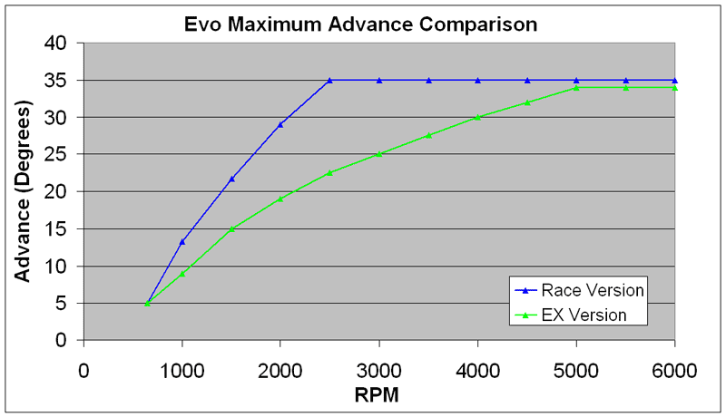
The EX versions are suitable for all street driven applications, including large displacement and high compression engines where spark timing must be retarded from stock settings to avoid destructive engine detonation. As a compliance criteria, the Air Resources Board allows products such as the our EX versions to advance ignition timing up to 4 degrees beyond the original equipment module. Thus the maximum advance curve in the EX versions is still very aggressive and allows a performance improvement when using 92-93 octane gasoline with stock engines.
The maximum advance curve for the race versions are only suitable for true race engines where a long duration/high overlap camshaft reduces cylinder pressure in the lower RPM range and high octane race gasoline is used.
Both the EX and race versions of our ignitions have sufficient advance adjustment range for most applications using the advance slope switch settings. When used with our PC Link Evo software, both the EX and race versions allow creating a custom advance curve and no limitation exists on retarding the spark timing to solve a detonation problem which is the most common reason for creating a custom curve.
What is the difference between single fire and dual fire?
Single fire and dual fire refers to the number of times the spark plug fires during each four stroke cycle. The terminology is somewhat unique to Harley-Davidson® engines and is by no means consistently applied. For example, Custom Chrome Industries, one of the largest distributors of Harley-Davidson® aftermarket parts, uses the opposite terminology. Their single fire systems correspond to what most other companies refer to as dual fire.
With the exception of the new Twin-Cam 88 and late model Sportster 1200 engines, all carbureted Harley-Davidson® engines have been dual fire. A single coil winding with two high voltage output terminals fires the spark plugs on both cylinders simultaneously. Each plug is fired twice during each four stroke cycle. This approach was used to cut costs as it eliminates the need for a distributor or a second coil and additional electronics. Dual fire results in a number of potential problems.
Most late model automotive engines are distributorless. Many of these engines use coil packs where a single coil winding fires two spark plugs. When one spark plug fires on the compression stroke the other spark plug is firing on the exhaust stroke. This approach is termed “wasted spark” and is widely used. The wasted spark always occurs on the exhaust stroke because the engines have even firing intervals (i.e. 90° for a V8) and cylinders are always paired so that the pistons are 360° out of phase (i.e. one on the compression stroke when the other is on the exhaust stroke). The wasted spark causes little energy loss and no harmful effect on the exhaust stroke.
The situation is quite different with a dual fire ignition on a Harley-Davidson® V-twin engine with 315° and 405° firing intervals. The graphic below shows what occurs. When the rear cylinder is fired on the compression stroke, the front cylinder is on the exhaust stroke – which is OK. But when the front cylinder is fired on the compression stroke, the rear cylinder is already on the intake stroke! Under some conditions, a combustible mixture may exist in the rear cylinder at this point and the wasted spark causes a backfire through the carburetor. Long duration camshafts and improper carburetor jetting can contribute to the problem. Additional information on this subject may be found on the Mikuni web site.
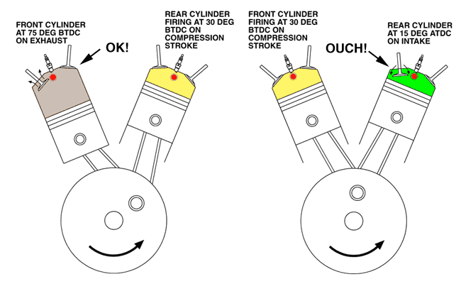
The Problem with Dual Fire Ignition
A single fire ignition eliminates the backfire problem and enhances idle quality. The single fire ignition uses separate coil windings and electronics to fire each spark plug independently. Spark firing occurs only on the compression stroke. Conversion of older carbureted Harley-Davidson® engines to single fire is highly recommended. There is no downside to single fire, other than the cost of the conversion.
Twin Tec Models 1005, 1006, and 1007 have switch selectable single and dual fire operating modes. You can initially install one of our units and run in dual fire mode with your original equipment coil. You can then easily upgrade to single fire by adding an appropriate coil. If you have a tach, it will continue to operate properly when connected to the tach output from the Twin Tec ignition (some competitive systems require that you purchase a tach adapter).
What dual fire coil is recommended for Twin Tec Model 1005, 1006, and 1007 ignitions?
If you read the section above, you understand the drawbacks inherent with dual fire. Don’t waste money on another dual fire coil. Spend a few dollars more and buy a single fire coil. All the Twin Tec ignitions for Evolution® and Shovelhead® engines have switch selectable single fire mode, so all you need is a single fire coil.
What coil is recommended for single fire conversion with Twin Tec Model 1005, 1006, and 1007 ignitions?
Single fire coils consist of two independent coil sections combined together in one housing. The coil primary resistance should be in the 3 ohm range. Make sure you don’t buy a coil intended for Twin Cam 88® applications as these have low .5 ohm primary resistance and will not work properly. Our part number 2005 coil is an excellent choice for use with all Twin Tec single fire ignitions.
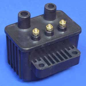
High Output Single Fire Coil P/N 2005
Ignition coil manufacturing has gone overseas to China. That is an economic reality we can’t change. What we can do differently is to be honest about it and pass the savings on to you. Right now, one factory supplies Screaming Eagle® and several of the aftermarket companies, including Crane and Dyna. Contrary to various claims, the coils are all basically the same and just differ in cosmetics. Screaming Eagle® 31746-98A (black), 31748-98A (red), and 31750-98A (orange) have a bulky connector and may not fit some stock covers. Crane and Dyna coils are packaged in a slightly smaller housing with conventional screw terminals. We contracted with another factory to build a similar coil shown above.
What if I have dual spark plug heads?
Twin Tec Model 1005, 1005S, 1006, or 1007 ignitions can be used in dual spark plug head applications. Please refer to the Dual Spark Plug Tech Note for further information.
Can I automatically retard timing with a turbocharger or nitrous oxide injection system?
Yes! This is possible with Twin Tec Model 1005, 1006, and 1007 ignitions. You will require the optional PC link cable and software. You can easily reconfigure the VOES switch input as a retard input. You can program the retard value over a 0-10° range. When the retard input is grounded, ignition timing is automatically retarded.
For a turbocharger application, you can simply replace the VOES switch with a pressure activated switch. For nitrous applications, use a relay. Connect the relay coil in parallel with the solenoid valves and use a normally open contact to ground the retard input whenever the solenoid valves are energized.
For more detailed information, please download our Turbo Boost and Nitrous Timing Retard Tech Note.
What is the VOES switch?
When is an ignition power relay recommended with single fire installations?
Some motorcycles with high compression or large displacement engines and Twin Tec Model 1005, 1005S, 1006, or 1007 single fire installations may exhibit difficult starting. The starter motor draws more current than the electrical system was originally designed for. The voltage at the battery terminals may drop to around 6 volts during cranking. The single fire coil also draws more current and an additional 1-2 volt drop may occur in the long length of wire between the battery, engine stop/run switch, and the coil. Under these conditions the voltage at the coil may be so low that the spark energy is insufficient to fire the engine. Motorcycles more than a few years old may have slightly corroded switch contacts, further aggravating the problem. The solution is to install an ignition power relay kit. The relay is controlled by the engine stop/run switch and supplies full battery voltage direct to the coil. You can order the ignition power relay kit direct from Twin Tec, or you can download the instructions and purchase a standard 12 volt automotive relay from most parts stores.
What is the VOES switch?
The VOES switch senses manifold pressure. Most carbureted H-D® models manufactured from 1980-98 and some later Sportsters® use a VOES switch to increase ignition timing advance during idle and cruise conditions. When manifold pressure (MAP) drops, the normally open VOES switch closes and connects the ignition module’s VOES input (violet/white wire) to ground. The green VOES LED will illuminate. The ignition module then uses the low MAP advance curve. If you look at the advance curves published in our instructions, you will see that the low MAP curves are somewhat more aggressive than the wide open throttle (WOT) curves. The additional advance stabilizes the idle and improves cruise fuel economy. The VOES switch has no effect on wide open throttle (WOT) operation.
During normal operation, the green VOES LED should illuminate during idle. If you have installed a high performance camshaft or made other major modifications, manifold pressure may run higher at idle. In this case, the green VOES LED will not illuminate at idle. You should still see the green VOES LED momentarily illuminate if you rev the engine up to about 2,500 RPM and then close the throttle.
We recommend that you leave the VOES switch connected. If you have a motorcycle where the VOES switch was removed, we recommend that you replace it. We offer P/N VOES-KIT-MC7. This is a complete kit with mounting bracket and has a vacuum switching level of 6-7 in-Hg that helps eliminate spark knock under light load or throttle roll-on.
Can I automatically retard timing with a turbocharger or nitrous oxide injection system?
Yes! This is possible with Twin Tec Model 1005, 1006, and 1007 ignitions. You will require the optional PC link cable and software. You can easily reconfigure the VOES switch input as a retard input. You can program the retard value over a 0-10° range. When the retard input is grounded, ignition timing is automatically retarded.
For a turbocharger application, you can simply replace the VOES switch with a pressure activated switch. For nitrous applications, use a relay. Connect the relay coil in parallel with the solenoid valves and use a normally open contact to ground the retard input whenever the solenoid valves are energized.
For more detailed information, please download our Turbo Boost and Nitrous Timing Retard Tech Note.
Several competitors’ internal (nose cone) modules have failed on my engine. Will the Twin Tec Model 1005 be more reliable?
It depends on the cause of the failure. Besides obvious physical damage, the most common causes are excessive temperature and over-voltage. If several modules have failed within a short period of time, you have to step back and try to identify the underlying cause. The following sections cover heat and over-voltage related failures.
Diagnosing and solving heat related failures.
Heat kills electronics. All the major suppliers use the same type of electronic devices rated for operation at 105 deg C (221 deg F), the highest rating available. The Model 1005 can tolerate somewhat higher temperatures, but exposure to temperatures above 125 deg C (257 deg F) will greatly reduce life expectancy. We sometimes see problematic applications where several module failures have occurred. The failure mode is a classic thermal intermittent where the module stops firing one cylinder when it gets hot. We have found that these problematic applications share one or more of the following characteristics:
- VOES switch removed or non-functional. Without vacuum advance at idle and part throttle, thermodynamic efficiency is reduced and engine temperatures increase significantly.
- Improper carburetor jetting resulting in lean air/fuel ratio (AFR). A lean AFR will cause the engine to run very hot. All performance engine modifications necessitate carburetor rejetting. Carburetors are never correctly jetted out-of-the-box. The only practical means of correctly jetting a carburetor is to test the motorcycle on a chassis dyno equipped with an exhaust gas sniffer or to use our WEGO system.
- Lack of an oil cooler on a 95 CID or larger engine.
Exhaust pipe without heat shield in close proximity to nose cone.
Model 1005 units manufactured after January, 2006 include an internal temperature sensor. These units log elapsed time in various temperature bands up to 150 deg C. You can download this data with our Operating Statistics software.
You can easily diagnose potential overheating problems by using an infrared thermometer to check the module temperature. Remove the nose cone cover and place several strips of black electrical tape on top of the module to provide a target for accurate readings (infrared thermometers will not give accurate readings from reflective surfaces). Operate the motorcycle for at least 20 minutes and take an immediate reading after shutting off the engine.
Some high output engines may be poor candidates for an internal ignition and an external module such as our Model 1007 should be considered.
Model 1005 Extreme Over-Heating Damage
My engine runs too hot for an internal ignition. How do I convert to an external module?
If you have a H-D® model and the original wire harness is still intact, you can exchange your failed ignition for our Model 1006 or Model 1007 external plug-in module as appropriate for your application. You will also require the cam timing sensor. If you no longer have it, you can purchase H-D® P/N 32400-94 from your local dealer.
If you have a custom bike or your original ignition harness has been removed, you can purchase wiring harness kit H-D® P/N 32408-90 and cam timing sensor H-D® P/N 32400-94 from your local dealer and use these items along with our Model 1006 external plug-in module. The wire color codes are the same as shown in our Model 1006 installation instructions. Please note that this wire harness kit comes with a 7 terminal connector that will only mate with the Model 1006, it cannot be used with the Model 1007.
We offer special discounted pricing for Model 1006 and Model 1007 units exchanged for failed internal ignitions, regardless of the original manufacturer. Please call us at 386-304-0700 for details.
Diagnosing and solving failures caused by electrical system over-voltage.
Failure from electrical system over-voltage causes a surge absorber inside the Model 1005 to burn up. This failure mode can be readily identified by a characteristic raised and burned area on the back side of the unit as shown in the picture below and a strong odor of burned electrical insulation.
Model 1005 Over-Voltage Damage
The most common cause of this failure is momentary disconnection of the battery while the engine is running. The system voltage then spikes up to a very high level (over 30 volts) before the voltage regulator can react. It is not unusual to also find other damaged electrical components, such as burned out light bulbs or a dead radio on touring models. The problem is generally caused by defective or loose battery cables, improper battery ground connections, or internal defects in the battery. You must correct the underlying problem before installing a new module, otherwise the same failure will occur again. We suggest the following steps:
- Replace the battery. Even new batteries can have internal defects that cause an intermittent open connection between cells when the battery is subjected to vibration or shock.
- Replace all battery cables. The battery negative terminal must make a direct connection to frame ground. Some custom motorcycles route the battery negative cable to the engine and then rely on the engine mount to make a frame ground connection. This is never acceptable.
- Temporarily replace the electronic ignition with a mechanical breaker point system. Breaker points can withstand momentary electrical overvoltage conditions without catastrophic failure. Make sure you use an appropriate 5 ohm dual fire coil. Single fire or 3 ohm coils are not compatible with breaker points.
- Check the charging system. While not the underlying cause, the voltage regulator may also have been damaged. Verify that the battery voltage doesn’t exceed 14.4 volts when the engine is running in the 2,000-3,000 RPM range.
- Operate the motorcycle for several weeks. If no other electrical failures (such as a burned out headlight) are noted, it is probably safe to install a new electronic ignition module.
What is the proper orientation for the timing rotor and Model 1005 ignition module?
This question sometimes comes up in custom applications. The Model 1005 series (including the Model 1005S EX) requires H-D® P/N 32402-83 timing rotor. This timing rotor has two slots. The Model 1005 series cannot be made to work with any other type of timing rotor. The timing rotor must rotate counterclockwise (CCW). The Model 1005 series cannot be made to work in any applications where the timing rotor rotates clockwise. Correct orientation of the timing rotor is shown in the figure below. This is a top view showing an exploded Model 1005 for reference and the orientation of the timing rotor with respect to the Hall Effect sensors when the engine is on top dead center (TDC) on the front cylinder compression stroke.
Model 1005 Timing Rotor Orientation